Weiser SMARTCODE5 Instrucciones de montaje


1 2
3 4
5 6
7 8
9 0
UP
Copyright © 2009 Black & Decker Corporation
25605-02 Weiser SmartCode Manual
Program
Button
Mounting
Holes
Turnpiece
Lock
Button
Cylinder
Settings
Switch
Panel
Keypad
LED
Cylinder
Getting Started
1
Quick Reference
●Referto“QuickReference”areaandillustrationstoidentifycomponents.
●Preparedoor,peradditionalinstructions(included)beforeinstallingunit.
●IMPORTANT:Readinstructionscompletelybeforebeginninginstallation.
Use the checklist below to assure completion of important steps.
□ATTACHCONNECTOR..........................................
□RUN“BOLTDIRECTION”DETERMINATION.......
□PROGRAMCODE(S).............................................
□VERIFYOPERATION.............................................
Section 5
Section 8
Section 9 a, b, c
Section 9 d
Installation&ProgrammingManual
Interior
Assembly
Interior
Cover
Exterior
Assembly
Adapter
Bolt
Mounting
Plate
Mounting
Bolts
Interior
Assembly
Exterior
Assembly

2-3/8"
(60mm)
or
2-3/4"
(70mm)
1-1/2
(38mm)
hole
2-3/4" (70mm)
1.InstalllatchandStrike.
Fig.3
Fig.1
d.Leavetheboltintheextendedposition.
e.Installstrikewithtwo1-1/2”(38mm)woodscrews
(seegure5).
2.Removecoverandbatterycase.
2
Area Crank
a.Determineyourbackset,see
gure1.
b. Ifa2-3/4”(70mm)backsetis
required,extend bolt and adjust
latch as shown.(Seegure2).
Fig.2
Fig.5
Fig.4
c.Installlatch,securingwithsmall
woodscrews(seegure3).Note:
For a 1-1/2” (38mm) diameter
hole, test if latch extends and
retracts smoothly. Area indicated
may require addition clearance for
crank of latch to function properly
(see gure 4).
a.Removecoverfromassem-
blybyslidingcoverupandoff,
seegure.6
b.Removethebatterycase
frominteriorassemblybylift-
ing the case up and out and
setaside,seegure7.
Fig.7
Fig.6
Importantbeforeproceeding:
1. Verifythatposition#2ofthe“SettingsSwitch”isintheOFF posi-
tion.(Refertosection10.)
2. Workwiththedooropen(awayfromjamb)toavoidaccidental
lockout.
3.Makesuretheboltisintheextended(locked)position.
UP
KEEP
PARALLEL
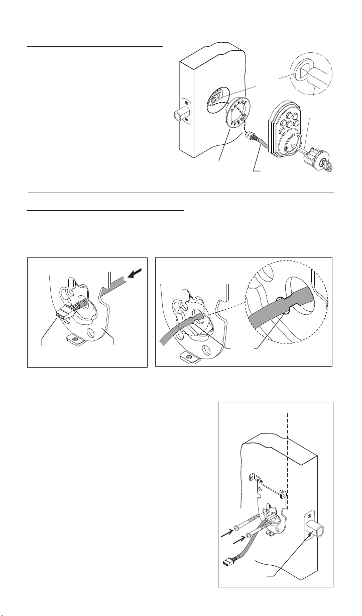
3.InstallExteriorAssembly.
Bolt
3
Wire
Harness
Adapter
For2-1/8”
diameteronly.
Fig.10
Fig.9
Fig.8
a. Placeadapterondoorasshown,
(note,adapterisnotrequiredif
mountingona1-1/2”(38mm)
diameterhole.
Crank
Torque
Blade
c. Placeassemblyondoor,threading
thewireharness(throughadapter-if
used)andunderthelatch.
b.Insertcylinderintoexterior
assembly.Withkeyincylinder,
rotatethetorquebladetoalign
withcrankinlatch.
a. Carefullyinserttheconnectorofthewireharness-throughthecenter
holeofthemountingplate(seegure8).
e.Checktheverticalalignmentformounting
plate and exteriorassembly.(Seegure10.)
h.Repeatasrequired.
f.Test.Usingthekey,retractandextendthe
boltafewtimestotestforsmoothaction.
c. Slide wires through the notch until mounting
platesitsushagainstdoor.
4.InstallInteriorMountingplate.
Mounting
Plate
Connector
b.Important,oncetheconnectorhaspassedthroughthecenterhole,tuck
thewireharnessoutofthewaybypressingitintothenotchholeasshown
ingure9.
Notch
Hole
d. Making sure that exteriorassemblyand
cylinderarepressedushagainstexterior
door,insertmountingboltsandtighten.
g.Ifactionfeelsrough,loosenscrewsand
re-alignthemountingplateandtheexterior
assembly.Note:Alsoseestep1-cforpossible
crankinterference.

Wire Harness
Small
Screws Torque Blade
Important Note: To prevent damage, always handle the wire harness
at the connector (do not pull wires).
4
Routewiresdown-avoidingany
excessbulgeatcurve,whichcould
interferewithbatterypackinstallation.
5.AttachtheConnectortotheInteriorAssembly.
Connector Port
Interior
Assembly Connector
Connector
Notch
Slot
a. Makingsurewiresareclearofpinchingandwireharnessisroutedas
shown,placetheinteriorassemblyondoor,aligningtorquebladeinsidethe
turnpieceshaft.
6.InstallInteriorAssembly.
Turnpiece
Shaft
b.Onceushondoor,
insert and tighten small screws
tosecureassemblyontothe
mountingplate.Note: To aid insertion of screws,
approach the screw holes with the screw loaded onto the screwdriver.
Note: Turnpiece may be difcult to turn until step 8 “Automatic - Bolt Direc-
tion Determination” is completed.
a.Aligntheconnectorwiththeconnectorportoftheinteriorassembly,
matchingnotchtoslot.
c.Oncealigned,pushtheconnectorinrmlytoconnect.
b.Foreasierorientation,viewthealignmentofconnectionfromthetopof
theinteriorassembly.
Top view

AA
1
2
-+
5
1
2
EXTERIOR
INTERIOR
8.Automatic-BoltDirectionDetermination(DoorHanding).
IMPORTANT:DONOTSKIPTHEFOLLOWINGSTEP.
LOCKWILLNOTBEABLETOOPERATEPROPERLY!
● In the steps below, the SmartCode mechanism automatically
determines the “door handing” and sets the proper direction for mo-
tor to rotate. The system will drive the bolt several times during this
process.
a.Pressandholdthe“LOCK”buttonontheexteriorkeypad,whilefully
insertingthebatterypackintotheinteriorassembly(thetabonthepack
mustfaceout-seeillustration).Holddownlockbuttonuntilyouhear2
beeps(about20seconds).Itisveryimportantthatthisprocessis
allowedtonishproperly.
7.Installbatteriesintobatterypack.
AlkalineBatteryWARNING:Donotdisposeofinre,recharge,
putinbackwards,disassemble,mixwithusedorotherbatterytypes.May
explodeorleakandcausepersonalinjury.
a. Install4newAAAlkalinebatteries.
Installthenewbatteriesasindicatedinillustration.Makesure
batterieslieatinholder.For best performance,
rechargeable batteries are not recommended.
Note: Do not install battery pack into unit until you start step 8.
LOCK
Button
Tab
Battery Pack
LED
Continued

1 2
3 4
5 6
7 8
9 0
Howthekeypadworks:
Eachbuttonrepresentstwonumbers(i.e.1and2fortherstbutton).You
onlyneedtopushthebuttononcetogeteither1or2.Forexample:If
yourcodeis1-2-5-6-8,
■Pressthe
1 2
buttononcetogetnumber1.
■Pressthe
1 2
buttononcetogetnumber2.
■Thenpressthe
5 6
buttononcetogetnumber5.
■Thenpressthe
5 6
buttononcetogetnumber6.
■Finallypressthe
7 8
buttononcetogetnumber8.
1 2
3 4
5 6
7 8
9 0
6
b.Notethattheturnpieceisfunctioningproperlywhenitisslightlyawayfrom
theverticalpositionwhenlockedorslightlyawayfromahorizontalposition
whenunlocked.
8.Continued.......
a. Presstheprogrambutton on the interior unit once.
b. Enterin4to8digitcodeontothekeypad.
c.Pressthe“LOCK”buttontosavecode.
d.
9.ProgrammingaUserCode.
● A programmed code can be from four (4) to eight (8) digits long.
●For maximum security an 8 digit code is recommended.
●Up to 2 user codes can be entered.
●Excess delay in the programming steps once started will cause unit to
beep twice and will require you to restart from step (9a) below.
Programmingthe1stusercode.
Extendtheboltbypressingthe“LOCK”buttonandre-enterthecode
to test.Theboltshouldretracttotheunlockedposition.Ifitdoesnot
unlock,repeatsteps(a)through(c).
LOCKED LOCKED
UNLOCKED UNLOCKED
TURNPIECE TURNPIECE
Program
Button
LOCK
Button
Continued

7
9.Continued.......
a. Presstheprogrambutton on the interior unit twice.
b. Enterin4to8digitcodeontothekeypad.
c.Pressthe“LOCK”buttontosavecode.
d.
Note: Programming instructions can also be found on interior of lock.
Programmingthe2ndusercode.
Extendtheboltbypressingthe“LOCK”buttonandre-enterthecode
totest.Theboltshouldretracttotheunlockedposition.Ifitdoesnot
unlock,repeatsteps(a)through(c).
10.SmartCodeUserSelectableSettings.
Switch #2 EnablestheAUTOLOCKwhen
intheONposition.WithAutoLockenabled,
SmartCode will automatically relock the door
(extendthebolt)30secondsafterunlocking.
Switches
ON
1 2 3 4
LED
Switch #1 StatusLEDblinksevery
5secondswhenintheONposition.Note:
The low battery RED LED cannot be
disabled.
Switch
Position
OFF
ON
LED
Color
Green
Orange
Red
Unlocked
Locked
Low Battery
Lock
Status
Red Low Battery
Hint: for easier access, use a ball point pen to operate the switches.
Switch #4 ExtraswitchwithNOFUNCTION.
Switch #3 EnablestheAUDIOsound(Beeper)whenintheON
position.Keypadwillnowlightred/greenwhenbuttonsarepressed.
CAUTION:Preventunauthorizedentry.Thislockcanbeopened
usingtwodifferentcodesthatarerandomlysetatthefactory.Uponin-
stallationandset-up,replacebothofthesecodeswithyourown.Since
anyonewithaccesstothepowerboardcanchangethesecodes,you
mustrestrictaccesstothepowerboardandroutinelycheckbothcodes
toassuretheyhavenotbeenalteredwithoutyourknowledge.

Whenthedoorisinthelockedposition,pressthelockbuttontolightup
thekeypad.Ina“verylowbattery”conditionthekeypadwillnotlightup.
b.Keypadlightsignals
Incorrect Codes Entered – when three incorrect codes are entered into
theSmartCodethekeypadwillashredandthebeeperwillsoundfor
15seconds.Thekeypadwillnotallowimputfor60secondsafterwhich
youcanre-enteracodeandtryagain.
a.KeypadBackLight
●
●
●
●
●
Switch3off–thekeypadwillashredeverytimeyoupressabutton.
Low Battery Warning – Afteracorrectcodeisentered,thekeypadwill
ashredmultipletimesforapproximately3seconds.
Boltnotfullyextended–thekeypadwilllightupred,thebeeperwill
soundfor3seconds.Thiswillalarmtheusertotryandlockthedoor
again.
8
11.LowBatteryIndicators.
●Afteracorrectcodeisentered,thekeypadwillashredmultipletimes
forapproximately3seconds.
●Afteracorrectcodeisenteredtheunitbeepsmultipletimesforap-
proximately3seconds.
●Regardlessofswitch#1position,under“LowBattery”condition-red
LEDwillashevery5seconds.
1.TheinteriorLED
2.TheexteriorKeypad(whenswitch#3isOFF).
3.TheAudioIndicator(whenswitch#3isintheONposition).
Note:Forfuturebatteryreplacement,removebatterypack,replacebatter-
ies(seesection7)andsimplyreinsertbatterypackasshown,abeepand
aGreenLEDashwillindicateasuccessfulsysteminitialization.Nobolt
directiondeterminationisrequiredaftertheinitialinstallationunlessthelock
isre-installedonadifferentdoor.
WARNING:ThisManufactureradvisesthatnolockcanprovide
completesecuritybyitself.Thislockmaybedefeatedbyforcibleor
technicalmeans,orevadedbyentryelsewhereontheproperty.Nolock
cansubstituteforcaution,awarenessofyourenvironment,andcommon
sense.Builder’shardwareisavailableinmultipleperformancegrades
tosuittheapplication.Inordertoenhancesecurityandreducerisk,you
shouldconsultaqualiedlocksmithorothersecurityprofessional.
12.KeypadLights.

Forassistanceorwarrantyinformation:call
1-800-677-5625USA,1-800-501-9471CANADA
or visit, www.weiserlock.com
9
Q: IjustcompletedtheinstallationofaSmartCodeunitonmydoor;Iamunabletooperateit
manually,althoughIcheckedforsmoothboltoperationduringinstallation.WhatshouldIdo?
A: Youneedtorunthe“BoltDirection”routineagain;allowtheprocesstoruntocompletionsee
Section8inUser’sManual.
Q:Sometimes,whenIoperatethelockmanually,I“feel”abumpwhileturningtheturn-piece.
A: Oninstallationswheredooralignmentislessthanoptimum(Latchandstrikedonotquiteline
up)theSmartCodemaynotbeabletoFULLYextend(orretract)theboltwhencommandedto
doso.Thiscausestheelectro-mechanicalcomponentstogooutofsync.Tore-synchronizethe
system,performthefollowing:
1. Have the door repaired and aligned properly
2.OntheSmartCodeunitpushthe“Lock”button
3. On the Smart Code unit enter code to unlock
4. Theunitisnowsynchronized
Q:HowlongwilltheSmartCodeoperateonasetofbatteries?
A:Basedon15operationsperday,asinglesetofAlkalinebatterieswilloperatetheSmartCode
foroverayear.
Q:Whattypeofbatteriesdoyourecommend?
A:Forbestresults,usenewnon-rechargeableAlkalinebatteriesonly.
Q: IjustinstalledaSmartCodeonmydoorbutitdoesnotoperatecorrectly
A: Thisisprobablyduetoincorrectorincompleteinitialization.Pleaseperformthefollowing:
a.Removethebatterypack
b.OntheInteriorunit,press“Program”buttonthree(3)times
c. Wait at least 10 seconds
d.Refertosection8,“BoltDirectionDetermination”.
Q: Iremovedthebatterypackmomentarilyandmylockdoesnotworkanymore.
A: Thesystemdidnotinitializeproperlyduetoremainingcharge.Tocorrectperformthefollow-
ing:
a.Removebatterypack
b.Press“Program”buttonthreetimes
c.Wait10seconds.
d.Insertbatterypack.
e.ThesystemshouldashtheGreenLEDandbeep,indicatingproper
initialization
f.Repeata-difinitializationfailed
Q:Iamplanningtobeawayforseveralmonths;willmylockoperatewhenIgetback?
A:Whenthesystemisidling,itconsumesminimumpower(veryclosetobatteryshelflife.)With
alkalinebatteries,thelockshouldbeoperableafteryearsofidle.SeealsoQuestionsandAnswers
below.
Q:Ireplacedmybatterieslessthanayearagoandneedtoreplacethemagain.
A:Checkdooralignment.IftheSmartCodemakesseveralattemptstolockorunlockthedoor,it
maymeanthatthedooriswarpedoritdoesnotlineupcorrectlywiththestrike.Operatingthelock
multipletimesreducesbatterylife.Avoidturningonthekeypadlightunnecessarily.
Q:WhatsettingsshouldIusetogetthemaximumbatterylifeoutofmylock?
A:Set“StatusLED”(SW1)and“Auto-lock”(SW2)totheoffposition.
13.FrequentlyaskedQuestions(FAQs).
This product is covered by one or more of the following patents or patents pending: 5123683 5317889 5335525 5335950 5441318 5452928 5482335 5490700 5496082 5513509 5513510
5529351 5540070 5570912 5662365 5761937 5810402 5816629 5857365 6058746 6128933 6151934 6398465 6401932 6412319 6443504 6532629 6536812 6568727 6598440
6662606 6695365 6702340 6745602 6828519 6860131 6860529 6862909 6871520 6880871 6948748 6951123 6959569 6971513 6973813 7007528 7100408 7104098 7114357
7117701 7152891 7156432 7162901 7213429 7234331 7308811 RE38693 D344011 D347564 D348602 D348821 D352888 D361488 D361489 D361706 D363872 D373063 D373523
D400777 D407292 D431443 D435423 D436933 D437216 D437771 D443194 D443808 D446122 D447927 D452131 D453897 D453898 D453899 D454049 D458839 D461700 D463968
D464565 D464877 D465989 D468636 D472794 D473780 D514921 D524630 D525512 D525516 D540140 D540147 D541621 D542115 D545169 D547830
Tabla de contenidos
Idiomas:
Otros manuales de Cerrar de Weiser

Weiser
Weiser Aura Manual de usuario

Weiser
Weiser Smartcode 5 Manual de usuario

Weiser
Weiser kevo Touch-to-Open Manual de usuario

Weiser
Weiser Smartcode 10 Manual de usuario

Weiser
Weiser HALO Manual de usuario

Weiser
Weiser Smartcode 5 Manual de usuario

Weiser
Weiser Kevo Manual de usuario

Weiser
Weiser PREMIS Manual de usuario

Weiser
Weiser 62841/01 Manual de usuario


