Wavetek MS1200 Manual de usuario

1
WavetekWavetek
WavetekWavetek
Wavetek
Communications Division
5808 Churchman Bypass
Indianapolis, IN 46203-6109
(800)851-1198
(317)788-5960
Fax: (317)782-4607
8/95
Manual Part No.
6510-00-0281
This document contains information proprietary to
Wavetek. The information in this document
is not to be used or duplicated in any manner without
the prior approval, in writing, of Wavetek.
OPERATION MANUAL
MODEL MS1200
SCANNING SIGNAL
LEVEL METER

2
WARRANTY
Wavetek warrants that all Products manufactured or procured by Wavetek conform to
Wavetek’s published specifications and are free from defects in materials and workmanship
for a period of one (1) year from the date of delivery to the original Buyer, when used under
normaloperatingconditionsand withintheserviceconditionsforwhichtheyweredesigned.
This warranty is not transferrable and does not apply to used or demonstration products.
The obligation of Wavetek arising from a Warranty claim shall be limited to repairing, or at
its option, replacing without charge, any assembly or component (except batteries) which in
Wavetek’s sole opinion proves to be defective within the scope of the Warranty. In the event
Wavetekisnotabletomodify,repairorreplacenonconformingdefectivepartsorcomponents
toa condition aswarrantedwithin a reasonabletimeafter receipt thereof,Buyersshall receive
credit in the amount of the original invoiced price of the product.
Wavetek must be notified in writing of the defect or nonconformity within the Warranty
period and the affected Product returned to Wavetek’s factory, designated Service Provider,
or Authorized Service Center within thirty (30) days after discovery of such defect or
nonconformity. Buyer shall prepay shipping charges and insurance for Products returned to
Wavetek or its designated Service Provider for warranty service. Wavetek or its designated
Service Provider shall pay costs for return of Products to Buyer.
Wavetek shall have no responsibility for any defect or damage caused by improper storage,
improperinstallation,unauthorized modification, misuse, neglect, inadequate maintenance,
accidentor for any Product which has been repairedor altered by anyone other than Wavetek
or its authorized representative or not in accordance with instructions furnished by Wavetek.
The Warranty described above is Buyer’s sole and exclusive remedy and no other warranty,
whether written or oral, expressed or implied by statute or course of dealing shall apply.
Wavetek specifically disclaims the implied warranties of merchantability and fitness for a
particular purpose. No statement, representation, agreement, or understanding, oral or
written,madebyan agent, distributor, or employee of Wavetek, which is not contained in the
foregoing Warranty will be binding upon Wavetek, unless made in writing and executed by
anauthorized representativeof Wavetek.Undernocircumstancesshall Wavetekbe liablefor
any direct, indirect, special, incidental, or consequential damages, expenses, or losses,
including loss of profits, based on contract, tort, or any other legal theory.
Extended Warranty Programs
Extended warranties and service contracts are available for new and currently owned
equipment for an additional cost. Contact the Customer Service Department (800 851-
1198) for details pertaining to extended warranties and service contracts.
Return Authorization Procedure
The customer MUST obtain a RETURN AUTHORIZATION NUMBER from the
Customer Service Department (800 851-1198) prior to returning any equipment for
warranty or non-warranty repair. Wavetek accepts no liability for any instrument or
subassembly returned to the factory without this number. Any correspondence regarding
returned instruments or subassemblies should be referenced to that number.

3
Contents
Introducing microStealth .................................................................... 5
Introduction .......................................................................................... 5
Getting Acquainted with the Keypad ................................................ 7
Getting Acquinted with the Screen ................................................... 9
The Navigator ...................................................................................... 12
Configuring microStealth .................................................................... 12
Global Configuration ........................................................................... 13
Measurements Configuration ............................................................. 16
Channel Plan Configuration ............................................................... 19
Using microStealth................................................................................27
Introduction .......................................................................................... 27
Installation ............................................................................................ 27
Selecting Channel Packages ...............................................................28
Selecting the Test Point ...................................................................... 28
Installation Results Summary ............................................................. 29
The Channel List ................................................................................ 30
The Pass/Fail Indicator ....................................................................... 30
Channel Measurement ........................................................................ 31
Printing an Installation Report ........................................................... 32
Level ..................................................................................................... 32
Adjuisting the Reference Level ......................................................... 33
Tuning by Channel .............................................................................. 33
Tuning by Frequency .......................................................................... 33
Measurement hold ............................................................................... 34
Printing the Screen .............................................................................. 34
Warning Indicators ............................................................................... 34
Full Scan ............................................................................................... 35
Moving the Marker.............................................................................. 35
Adjusting the Reference Level .......................................................... 36
Adjusting the Scale .............................................................................. 36
Zooming In and out ............................................................................. 36
Checking Limits .................................................................................. 36
Checking Limits on an Individual Channel .....................................38
Measurement Hold.............................................................................. 39
Printing the Screen .............................................................................. 39
Tilt ........................................................................................................ 39

4
Moving the Marker..............................................................................40
Selecting the Low and High Carriers ................................................40
Adjusting the Reference Level ..........................................................40
Adjusting the Scale ..............................................................................40
Measurement Hold..............................................................................40
Printing the Screen ..............................................................................41
Scan .......................................................................................................41
Moving the Marker..............................................................................41
Adjusting the Reference Level ..........................................................41
Adjusting the Scale ..............................................................................42
Checking Limits ..................................................................................42
Measurement Hold..............................................................................43
Printing the Screen ..............................................................................43
Reference ...............................................................................................45
Using the Reference Section ..............................................................45
Help .......................................................................................................45
Information............................................................................................46
Technical Support .................................................................................47
Appendix A: Specifications ..................................................................49
Appendix B: Power Management and Battery .....................................51
Battery Pack Location and Installation.................................................51
Charging the Battery Pack ....................................................................51
Battery Tips ...........................................................................................51
Appendix C: Interface Port ...................................................................53
Connector ..............................................................................................53
Cable Specifications ..............................................................................54

5
MODEL MS1200
1
Introducing
microSTEALTH
INTRODUCTION
The MS1200 Signal Level Meter is a high performance instrument
designed for cable television technicians. The durable, waterproof
MS1200 makes innovative use of a graphics LCD to simplify
operation. The LCD backlight makes measurements easier in
crawl spaces and behind TVs. The display is easy to see in bright
sunlight.
A scan mode allows you to see the levels of all carriers in a spectral
display. You can also view level measurements at a single fre-
quency or for a specific channel. When tuned to a channel, the
display indicates the levels of the video and audio carriers, and the
difference between the carrier levels.
When performing an installation, you can press the Installation
Check key to quickly verify that all channels are within limits that
you have defined. You can use this feature to determine whether
or not a subscriber connection meets FCC or other government
requirements.
A special channel plan building mode automatically determines
which channels are active on your cable system. Once the channel
plan is defined, you can copy it to multiple MS1200s using the
built-in serial port. Channel plans can also be created using
StealthWare, the Windows™ based data management package for
Stealth products, and downloaded to multiple MS1200s.

6
1
2
5
3
6
4
7
7

7
For documentation purposes, you can print any measurement
screen to a serial printer (Wavetek P-Stealth Printer). Following an
installation check, you can print an installation report that can be
filed with the work order. You can also print a report that lists all
configuration settings including the channel plan.
The MS1200 tunes from 45 to 550 MHz with an option to extend
the range to 5 to 890 MHz.
GETTING ACQUAINTED WITH THE KEYPAD
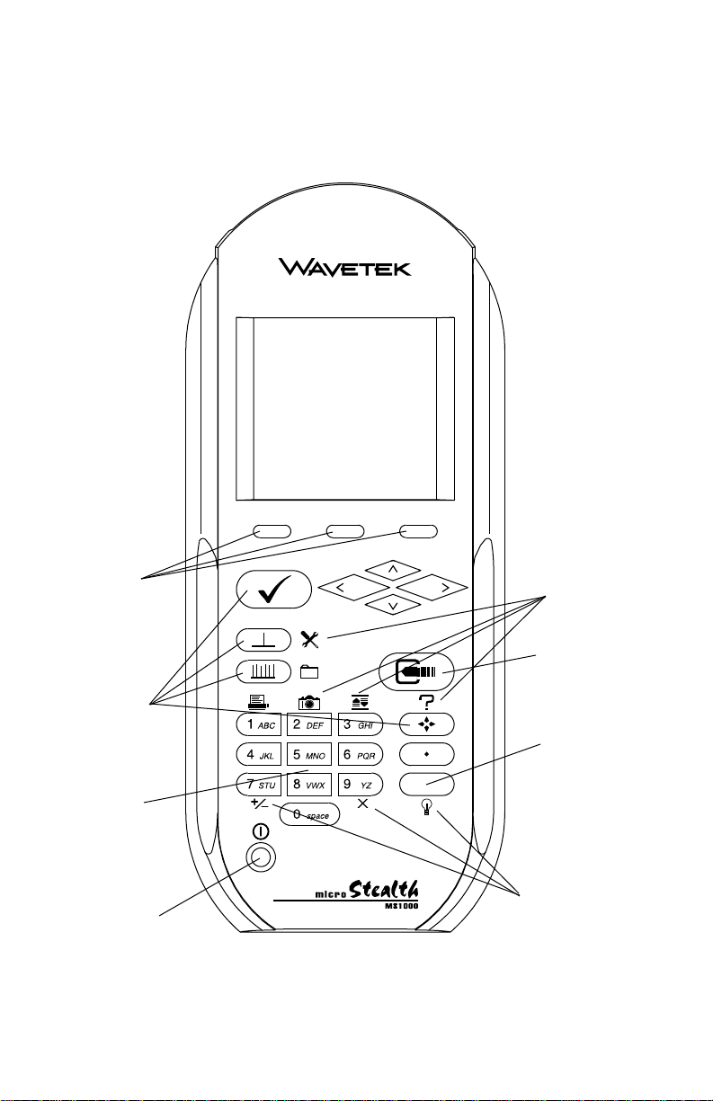
The keypad consists of the following:
• three Soft keys
• a Power key
• four Mode Selection keys
• an Enter key
• eleven Alphanumeric keys
• a Shift key
1. SOFT KEYS
There are three horizontally oriented soft keys located below the
display. The function of each soft key changes depending on the
particular operation being performed and is represented by an
icon immediately above the key.
2. POWER KEY - ON/OFF
Turns your microStealth on and off.
3. MODE SELECTION KEYS
INSTALLATION MODE
Easily check the channels that you have installed and
verify that they are within limits.
LEVEL MODE
Measure the signal level at a specific channel or fre-
quency.

8
FULL SCAN MODE
View a spectrum graph of all carrier levels in your channel
plan.
NAVIGATOR
Instantly "travel" to any mode using the NAVIGATOR.
4. ENTER KEY
Press this key to terminate your entry or selection.
5. ALPHANUMERIC KEYS
You use the alphanumeric keys to enter data while operating your
microStealth. Notice that these keys have a numeral and up to
three alphabetic characters labeled on them. You can only access
the characters when alphanumeric entry is allowed. In the
alphanumeric entry mode, you sequence through each character
and the numeral by repeatedly pressing the key. You can also
access a set of special characters that do not appear on the keypad
by using the up and down arrows. Once the desired character is
displayed, move the cursor to the next position using the right
arrow. Be sure to terminate your entry by pressing the key.
6. SHIFT KEY
Some keys perform more than one function. The secondary
function of a key is represented by an icon printed next to it.
Notice that the icons are color coded with the SHIFT key. You
access the secondary function by first pressing the SHIFT key
and then the associated key.
7. SECONDARY FUNCTIONS
CONFIGURE MODE
Configure your microStealth for your own specific needs.
AUTO REFERENCE
Let microStealth automatically set the reference level for
you.

9
SNAP SHOT
Hold the measurement. The measurement is retained even
if the cable is disconnected from the input.
CLEAR
Clear-out your entry and start over again.
BACKLIGHT ON/OFF
Quickly turn the backlight on when it is too dark to see the
display.
POSITIVE/NEGATIVE
Enter positive and negative values (when allowed).
HELP
View a description of each icon found in the current soft
key menu.
PRINT
Print a measurement screen, installation report, or
configuration report to a serial printer.
Note:
The following secondary function is not available on the MS1200:
FILE
GETTING ACQUAINTED WITH THE SCREEN
There are certain elements of the screen that will become familiar
to you as you use your microStealth.
The Title Bar
Notice the title bar at the very top of the screen. It presents the title
and icon for the current mode you are using.

10
Title Bar Indicators
You may see indicators appear above the title bar from time to time.
This is what they represent:
This indicator appears in the top right-hand corner of
the screen when you press the SHIFT key. This means
that microStealth interprets the next key that you press
to be a secondary function.
This indicator is displayed to warn you that the battery is
low. When you see this, recharge the battery or change to a
fresh one as soon as possible.
This indicates that the RF synthesizer has become
unlocked. If this condition persists, the unit may need
repair.
The Status Bar
Look for the status bar in the lower portion of the screen. It displays
a bar meter that indicates the charge remaining in your
microStealth's battery. When the battery meter reads low, you will
need to switch to a freshly charged battery soon.
Soft Key Icons
There are three soft keys located immediately below the display.
The function of a soft key is represented by the icon directly above
it.
Note
If the soft key function is not currently available, the icon appears
"grayed" or "dimmed".
Lists
Lists present several items for viewing and/or selecting. Notice that
the currently chosen item is highlighted. You can scroll through the
list using the up and down arrows.
Tabla de contenidos
Manuales populares de Comprobador de cables de otras marcas

Radiodetection
Radiodetection RD8100 Manual de usuario

Vonaq
Vonaq EasyCheck 900 Manual de usuario

Softing
Softing CableMaster CM200 Manual de usuario

Microtest
Microtest 8751 Manual de usuario

Psiber Data Systems
Psiber Data Systems 20 Manual de usuario

Platinum Tools
Platinum Tools LANSeeker TP500C Manual de usuario