Waterford E61 Guía de inicio rápido

FORYOURSAFETY
What to do if you smell gas:
!!
!!
!Do not try to light any
appliance
!!
!!
!Donottouchanyelectri-
cal switch: do not use
anyphoneinyourbuild-
ing.
!!
!!
!Immediately call your
gas supplier from a
neighbour's phone. Fol-
low the gas supplier's
instructions.
!!
!!
!Ifyou cannotreachyour
gassupplier,callthefire
department.
WARNING:
Improper installation, adjustment,
alteration, service or maintenance
can cause injury or property dam-
age.Refertothismanual.Forassist-
ance or additional information con-
sult an authorized installer, service
agency or the gas supplier.
FORYOURSAFETY
Donotstoreorusegasolineorother
flammable vapours and liquids in
thevicinityofthisoranyotherappli-
ance.
Installationandservicemustbeper-
formed by an authorized installer,
service agency or the gas supplier.
908-270 01/15/04
Owners &
Installation
Manual
FPI Fireplace Products International Ltd. 6988 Venture St., Delta, B.C. Canada, V4G 1H4
Tested by:
EMERALD GAS INSERT
ZERO CLEARANCE KIT
KIT # 270-900
PLEASE KEEP THESE INSTRUCTIONS FOR
FUTURE REFERENCE
WATERFORD
www.waterfordstoves.com
© Copyright 2004, FPI Fireplace Products
International Ltd. All rights reserved.

2Emerald Gas Insert Zero Clearance Kit
TABLE OF CONTENTS
GeneralInformation ...................................................3
ZeroClearanceKitSpecifications..............................3
ListingsandCodeApprovals .....................................3
ClearancestoCombustibles .....................................4
SafetyDecal .............................................................5
Framing.....................................................................6
ZeroClearanceKitAssembly....................................6
AssembletheCabinet ........................................7
AttachCabinet toFraming ................................10
InstalltheInsert ................................................11
VentingIntroduction ................................................11
SimpsonDura-VentComponentList .......................11
VentingArrangements-Horizontal..........................13
VentingArrangements-Vertical..............................13
HorizontalTerminationInstallation ...........................14
VerticalTerminationInstallation...............................15

Emerald Gas Insert Zero Clearance Kit 3
Emerald Insert Zero Clearance Kit Specifications
GENERAL INFORMATION
Using Kit# 270-900 you can convert the Emerald Gas Insert into a highly efficient heat producing Zero Clearance Fireplace.
This kit consists of factory built parts that require minimal assembly to form the Zero Clearance enclosure for the Emerald
Gas Insert. The enclosure can then be fixed into a framed combustible construction, and a standard Simpson Dura-Vent
Direct Vent GS System installed on the assembly for the required venting. The insert can be installed later. The faceplate
will normally overlap on top of the finished wall.
LISTINGS AND CODE APPROVALS
Thisgascomponenthas been tested in accordance with National Safety Standards, and has beencertifiedbyWarnockHersey
for installation and operation in the United States, and Canada as described in these Installation and Operating Instructions.
Check with your local building code agency before you begin your installation to ensure compliance with local codes, including
the need for "permits" and follow-up inspections. If any problems are encountered regarding code approvals, or if you wish
clarification on any of the instructions contained here, contact your local dealer.

4Emerald Gas Insert Zero Clearance Kit
CLEARANCES TO COMBUSTIBLES
The clearances for the Zero Clearance Kit are 0" to combustibles (back, side and floor) but when planning your installation
review the clearances required for the Insert (see below) after it is installed in the Zero Clearance Kit.
Warning: Combustible facing materials must not extend inside the 1/2" (13mm) lip at the edge of the face panels.
Any non-combustible facing materials (such as ceramic tile or masonry face brick) up to 1-1/2" (38mm) thick may be used
to finish the area inside the 1/2" (13mm) lip on the face panels. Non-combustible tile backer board such as Wonderboard or
Durock , or metal lath or screen may be fastened directly to the front of the face panels to provide a base for attaching facing
materials if needed. The Zero Clearance Kit must be installed on a flat, solid, continuous surface (e.g. wood, metal, concrete).
INSTALLATION
Emerald Insert Clearances to Combustibles:
From Unit
Sides A 12" / 305 mm
Unit to Unprotected Mantel B 16" / 406 mm
(see Mantel clearance diagram below)
Unit to Protected Mantel* C 12" / 305mm
In addition to these clearances, adequate accessibility
clearance for servicing and proper operation must be main-
tained.
Do not in any way obstruct the combustion air inlets that are
located on the front of the heater.
Floor Protection
If the appliance is installed in a fireplace that is elevated 5"
(127mm) or higher (i.e., a Waterford Zero Clearance Cabinet,
zero clearance fireplace, brick plinth, etc.), no floor protection is
required in front of the appliance.
Clearance from top of hob to
mantel and combustible trim,
unshielded.
Clearance from top of hob to
manteland combustible trim,
shielded.
*Mantel shield must have a
1" (25mm) air space be-
tween the mantel and shield
and a 1" (25mm) gap be-
tweenonthebackoftheshield
and the facing.
Combustibles are permitted within
the shaded area.
Combustibles are permitted within
the shaded area, on either side.

Emerald Gas Insert Zero Clearance Kit 5
This is a copy of the label that accom-
panieseachWaterfordE61ZeroClear-
ance Kit #270-900. We have printed a
copy of the contents here for your re-
view.Thesafetylabelis located on the
top panel.
NOTE: Waterford units are constantly
being improved. Check the label on
the unit and if there is a difference, the
label on the unit is the correct one.
SAFETY LABEL

6Emerald Gas Insert Zero Clearance Kit
INSTALLATION
EXTERIOR VENT TERMINAL LOCATIONS
A= Clearance above grade, veranda, porch, deck, or balcony *(min. 12"/30cm)
B= Clearance to window or door that may be opened *(12"/30cm)
C= Clearance to permanently closed window *(min. 12"/30cm)
D= Vertical clearance to ventilated soffit located above the terminal within a
horizontal distance of (24"/60cm) from the centerline of the terminal (min.
18"/46cm) check with local code.
E= Clearance to unventilated soffit (min. 12"/30cm)
F= Clearance to outside corner: with AstroCap Termination Cap (min. 6"/
15cm), with Dura-Vent Termination Cap (min.12"/30cm)
G= Clearance to inside corner: with AstroCap Termination Cap (min. 6"/15cm),
with Dura-Vent Termination Cap (min.12"/30cm)
H= Not to be installed above a meter/regulator assembly within (3'/90cm)
horizontally from the centerline of the regulator.
J= Clearance to service regulator vent outlet *(Canada: min. 72"/1.8m, USA:
min 36"/90cm)
K= Clearance to non-mechanical air supply inlet to building or the combustion
air inlet to any other appliance *(12"/30cm)
L= Clearance to a mechanical air supply inlet *(min. 72"/1.8m)
M= **Clearance above paved sidewalk or a paved driveway located on public
property *(min. 84"/2.1m)
N= Clearance under veranda, porch, deck, or balcony *(min. 12"/30cm)***
Note: * As specified in CGA B149 Installation Code. Note: Local codes or regulations may require different clearances.
**A vent shall not terminate directly above a sidewalk or paved driveway which is located between two single family dwellings and serves both dwellings.
***Only permitted if veranda, porch, deck, or balcony is fully open on a minimum of two sides beneath the floor.
.
BB
B
B
A
C
V
V
V
V
V
VV
A
A
V
Fixed
Fixed
Openable
Closed Closed
Openable
NL
B
E
B
M
D
F
K
H
j
Vertical
Termination
V
Vent terminal Area where terminal is not permited
A
Air supply outlet
24"
V
A
G
Inside
corner detail
V
24"
18"
Vertical
Termination

Emerald Gas Insert Zero Clearance Kit 7
Right Side
Base
Section
screw
screw
Left Side
Base
Section
screw
screw
Do not install the third screw until
the back panel is installed.
INSTALLATION
FRAMING
1) Thecabinetfacepanelshavea1/2"liptodefinethezonesforcombustible
and non-combustible facing materials: outside the lip, any material up
to 1/2" (13mm) may be used; inside the lip, only non-combustible
materials may be used (with a maximum thickness of 1-1/2" (38mm)).
The kit may be installed directly on and/or against standard combustible
building materials.
2) Frame in the enclosure for the Kit with framing material. The framed
openingfor theassembled kitis 52"(1321 mm)high x50-1/4" (1276mm)
wide x 18-1/2" (470 mm) deep. See diagram.
Iftheinteriorofthecabinetframingisfinished(withsheetrock,
for example), The dimensions given are from the inside of the
finished surfaces. The ceiling inside the framed enclosure
should be a minimum of 55-1/2" (1410mm) from the base of
the plinth.
3) For exterior walls, use a vapour barrier and insulate the
enclosure to the same degree as the rest of the house, or
according to local installation codes. In colder climates, if the heater is to be installed against an exterior wall or
chase, insulate the exterior walls according to local installation codes.
ZERO CLEARANCE KIT ASSEMBLY
Parts Included with Kit:
2 Back sections
2 Side
1 Base
1 Top
2 Front Face Side Panel
1 Front Face Top Panel
2 Top Standoffs
2 Extension Legs
1 Plinth
All pieces join together using the sheet metal screws that are
provided with the kit.
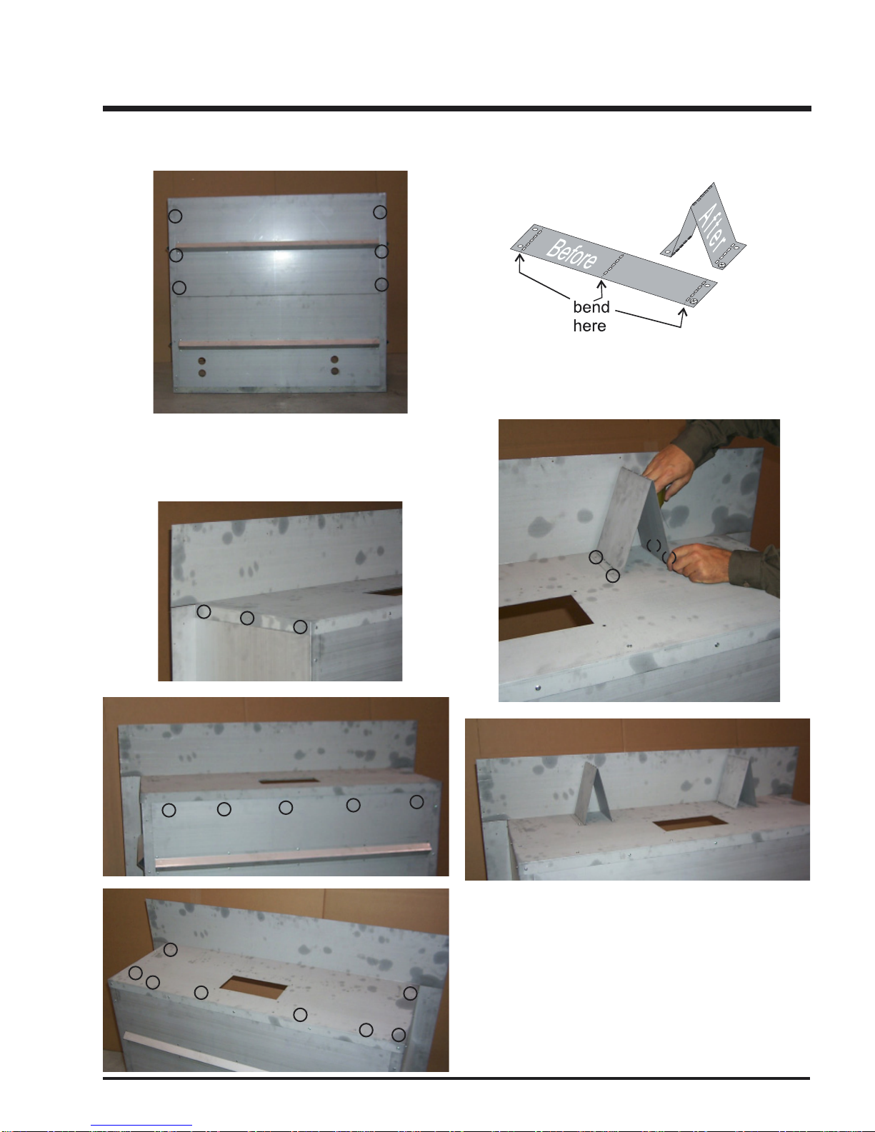
Assemble the Cabinet
1) Assemble the Sides and Base sections. The Side sec-
tionsfitinsidethelipoftheBasesection.Thewiderflange
on the Side section is on the front of the kit.
Secure with 2 screws on each side. Leave the 3rd screw
(closest to the rear) until the Back section is attached.

8Emerald Gas Insert Zero Clearance Kit
INSTALLATION
Secureto theLowerBack Sectionwith4 screws(from the
inside).
From the outside, secure with 2 screws on each side.
2) Set the assembled Side and Base sections upright. Slide
the Lower Back (the section with 4 holes) down the inside
of Side flanges (make sure the 4 holes are closest to the
floor - see photo).
Secure with 2 screws on each side, and 11 screws on the
back.
Right
Side
screw
Attach with 2 screws on the side. Repeat for Left Side
Attach with 11 screws on the side.
3) Slide the Upper Back Section down the inside of the Side
flanges.

Emerald Gas Insert Zero Clearance Kit 9
5) Assemble the 2 top Standoffs. The Top Standoffs are
shipped flat and must be folded at the bend lines into the
correct shape.
AttachtheRightStandofftothetopusingthe4holesatthe
frontright of the top.Install the Left Standoffto the 4 holes
at the front left.
6) Assemble the flue adaptor box. Slide the flex vent pipe
overthesmallventopeningonthebaseoftheadaptorbox
andsecurewithaclamp.Repeatforthe2ndflexventpipe.
Use silicone to seal the connection.
Left and Right Standoffs in position and
attached with 4 screws each.
Secure with 6 screws on the back. Leave the top screw
holes until the top is attached.
4) InstalltheTop.Holdthetopsothatthelargeverticalflange
is at the front of the cabinet and fit it down over the Side/
Back assembly. Secure the top to the assembly using 3
screws on each side and 5 through the back and 8 on top.
INSTALLATION

10 Emerald Gas Insert Zero Clearance Kit
INSTALLATION
8) Assemble the Face Panels (left, right, and top), all 3 Face
panels are installed loosely, and then attached to the
cabinet body.
Secure the Left and Right Panels to the top with 1 screw
each. Make sure that the outside edges are aligned.
Fit the assembled Side & Top Face Panels to the front of
the cabinet and secure with 19 screws.
7) Drop the Flue Adaptor assembly into the hole on the top
section and secure from the top with 4 screws.
Secure the flue adaptor box to the top with
4 screws from the top.
Este manual sirve para los siguientes modelos
1
Tabla de contenidos