WAREMA climatronic Control panel 3 Series Guía

Valid from 1st November 2016
2017717_b•en
Installation and connection
WAREMA climatronic®
Control panel 3.x

2017717_b•en•2016-11-01
We reserve the right to make technical changes
2
WAREMA climatronic® 3.x
Installation and connection
General information
The publication of this document supersedes all previous corresponding
documentation. We reserve the right to make changes in the interest of
technical progress. Particular care was taken in producing the text and
graphics in this document. In spite of this, we cannot accept liability for any
existing errors or the consequences thereof.
Legal information
Operating instructions, manuals and software are protected by copyright.
All rights to the software are specified in the license agreement included.
WAREMA climatronic is a registered trademark of WAREMARenkhoff SE.
WAREMA and the WAREMA logo are trademarks of WAREMARenkhoff SE.
All other brand or product names included in this document are trademarks
or registered trademarks of their respective owners.
Contact
Customer Center Control Systems
Sales, order processing and applied engineering
Tel. +49 (0)9391 20-3750 • Fax -3759
info.steuerungssysteme@warema.de
International
Tel. +49 (0)9391 20-3740 • Fax -3749
steuerungssyst[email protected]
Control Systems Helpline
Tel. +49 (0)9391 20-9317 • Fax -6769
Building automation systems sales
Dillberg 33, 97828 Marktheidenfeld
Tel. +49 (0)9391 20-3720 • Fax -3719
© 2016, WAREMA Renkhoff SE

2017717_b•en•2016-11-01 We reserve the right to make technical changes 3
Contents
Table of contents 1 Safety instructions........................................................................................... 5
1.1 Meanings of symbols and pictograms ............................................................5
1.2 Intended use .........................................................................................................6
1.3 Target group .........................................................................................................6
1.4 Retrofitting and modifications.............................................................................6
1.5 Installation and connection .................................................................................7
1.6 Working safely .......................................................................................................7
2 Scope of delivery ............................................................................................. 8
3 Planning ............................................................................................................ 9
3.1 Principal structure of a WAREMA climatronic system .................................9
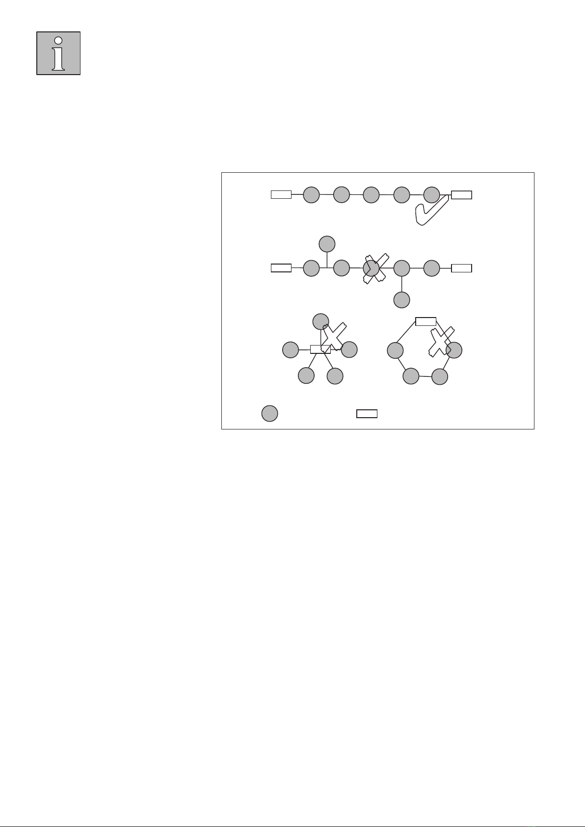
3.2 Network................................................................................................................ 10
4 Installation ...................................................................................................... 11
4.1 Procedure during installation........................................................................... 11
4.2 Installing base plate for control panel............................................................ 12
4.3 Installing weather station.................................................................................. 13
4.4 Install actuators .................................................................................................. 15
5 Connection ..................................................................................................... 16
5.1 Connecting control panel................................................................................. 17
5.2 Connecting weather station ............................................................................. 18
5.3 Connecting switch actuator 4M230/6M230 ................................................ 19
5.4 Connect hub ....................................................................................................... 23
5.5 Connection examples for custom products.................................................. 25
5.6 Dimensioning of the power supply ................................................................ 30
6 Commissioning .............................................................................................. 32
7 System components ...................................................................................... 33
7.1 Switch actuator 4M/6M AP/REG.................................................................... 34
7.2 Switch actuator 4MDC AP/REG...................................................................... 34
7.3 Switch actuator 16M230SMI AP/REG.......................................................... 35
7.4 Switch actuator 4M230I (vivamatic 3.0) AP/REG ..................................... 36
7.5 Switch actuator 4M230LS2Low AP/REG ................................................... 37
7.6 Dim actuator 2D AP/REG ................................................................................ 38
7.7 Sensor Interface................................................................................................. 50
7.8 Tableau Interface................................................................................................ 52
7.9 Sensor Splitter .................................................................................................... 54
7.10 Sensor Inside temperature / Humidity........................................................... 55
7.11 WAREMA climatronic WebControl................................................................ 56
8 Restoring the factory settings ...................................................................... 58
9 Technical data ................................................................................................ 59
10 Troubleshooting ............................................................................................. 60
10.1 Fault table............................................................................................................ 60
10.2 Checklist for checking the connection work................................................. 61
11 Index................................................................................................................ 63

2017717_b•en•2016-11-01
We reserve the right to make technical changes
4
WAREMA climatronic® 3.x
Installation and connection
Before you start
In these instructions you will find all the relevant information for installing and
connecting the components of a WAREMA climatronic system.
These instructions are subdivided into separate sections with symbols to
improve orientation. Proceed according to the order so that no problems
occur later when commissioning.
Safety
This section covers all the rules that you must observe so that your safety is
ensured and the WAREMA climatronic system functions safely and without
errors.
Information for installation and connection
When you install a WAREMA climatronic system for the first time, you will
find important basics here. These will help you to make the correct decisions
when installing and connecting.
Installation
Here you are led step by step through the installation of all the components
of the WAREMA climatronic system.
Connection
Here you will find all the information for connecting the WAREMA climatronic
components to each other and the controlled products safely and according
to their function.
Commissioning
For commissioning and setting the WAREMA climatronic please consult the
document with the art. no. 2017718.

2017717_b•en•2016-11-01 We reserve the right to make technical changes 5
1 Safety instructions
Read these instructions before installing and connecting the control.
Note the safety instructions; failure to do so will void any warranty claims
against the manufacturer.
Keep these instructions for future use.
1.1 Meanings of symbols and pictograms
The safety information contained in these instructions is marked with warning
symbols. They are categorised into different warning types depending on the
level of potential danger:
DANGER
warns of an imminently dangerous situation.
Possible consequences may include serious injuries and even death
(personal injury), property damage or environmental harm.
WARNING
warns of a potentially dangerous situation.
Possible consequences may include light or serious injuries and even
death (personal injury), property damage or environmental harm.
CAUTION
Reminder to exercise care.
Failure to comply may result in property damage.
The following pictograms and symbols may be affixed to the control unit itself
or to the connected devices, alerting you to potential danger:
WARNING
Warning against dangerous electrical voltage.
CAUTION
component damage due to electrostatic discharge.
The i symbol designates important information and helpful tips.
Example The term Example marks an example.
The square indicates an instruction or a prompt for action. Perform this
action.
The triangle denotes an event or the result of a preceding action.
The black triangle is a bullet point for lists or selections.
Safety

2017717_b•en•2016-11-01
We reserve the right to make technical changes
6
WAREMA climatronic® 3.x
Installation and connection
1.2 Intended use
The WAREMA climatronic is an electronic system for switching and con-
trolling different devices such as sun shading product equipment, lighting,
heating, cooling and ventilation equipment as well as window drives.
WARNING
Please obtain the written approval of the manufacturer for the connection
of devices not listed in these instructions.
1.3 Target group
These instructions address persons installing, wiring or connecting the
WAREMA climatronic, including all necessary parts, to the mains voltage.
WARNING
Installation, connection, commissioning or operation by insufficiently
qualified and knowledgeable persons may cause serious damage to the
system or even personal injuries.
Installation, connection and commissioning may only be performed by
trained qualified technicians. These technicians must be able to recognise
dangers that may be caused by the mechanical, electrical or electronic
equipment.
1.4 Retrofitting and modifications
WARNING
Retrofitting and modifications may impact the safety of the system or
reduce its effectiveness. Possible consequences may include death,
serious or light injuries, and property or environmental damage.
Contact us or your specialist dealer before retrofitting or changing the system
or the unit parameters.
Exercise special care when components of different versions are combined
or when existing components are replaced by older/newer products with a
different scope of functions or a different software version.

2017717_b•en•2016-11-01 We reserve the right to make technical changes 7
1.5 Installation and connection
WARNING
The electrical installation must be performed by a certified electrician
in accordance with the electrical installation regulations published
by the Association of German Electrical Engineers (VDE 0100) or the
standards and legal requirements of the country in which the device is
being installed. The electrician must observe the installation instructions
included with the supplied electrical devices.
All control devices are intended to be installed indoors unless otherwise
specified.
The applicable national standards and guidelines must be followed for the
control of lighting, heating, cooling and ventilating equipment.
Do not use this device to control doors, gates and garage door drives.
Window drives may only be controlled in compliance with the applicable
standards and national safety regulations (key points: safety distance, move-
ment speed, entrapment protection system, etc.)
Only fans approved for a dimming function may be dimmed.
1.6 Working safely
When performing work on motor-operated windows or building facades
where motor-operated sun shading products are installed:
WARNING
Danger to life and property damage through sudden movement of the
controlled products.
De-energise the unit
Sufficiently secure the unit against unauthorised and inadvertent reactivation.
Use suitable safety devices for personal protection
Do not place or store any items within the range of movement of
automatically operated mechanisms (e.g. ladder against a house wall with an
articulated arm awning)

2017717_b•en•2016-11-01
We reserve the right to make technical changes
8
WAREMA climatronic® 3.x
Installation and connection
2 Scope of delivery
Fig. 1 Scope of delivery
1WAREMA climatronic control panel
2Installation and connection instructions
3Commissioning and setting instructions
4Operation instructions
Base plate for the control panel with a fixing screw and nut
Accessories kit with:
Terminating resistance
Connection terminals
4 screws and screw anchors each for wall installation
USB cable to connect the control panel to a PC
Magnet for identification of the weather station
SD card for storing settings of the WAREMA climatronic incl. WAREMA
climatronic studio software and additional menu languages for loading onto
the control panel

2017717_b•en•2016-11-01 We reserve the right to make technical changes 9
3 Planning
3.1 Principal structure of a WAREMA climatronic system
WAREMA climatronic®
WAREMA climabus
Actuator Actuator
Sun shading
system
Sunblind
pushbutton
Light
pushbutton
Light
WAREMA climatronic®
weather station
230 V/50 Hz 230 V/50 Hz
Power supply unit
230 V/50 Hz
Fig. 2 Overview of the structure of a WAREMA climatronic system
The WAREMA climatronic is a complete solution for controlling all WAREMA
products and additional systems in a conservatory or in larger building
complexes.

2017717_b•en•2016-11-01
We reserve the right to make technical changes
10
WAREMA climatronic® 3.x
Installation and connection
3.2 Network
All components of the control communicate with each other via an RS485
bus system. Careful planning of the network prior to installation saves you
elaborate and time-consuming adjustment work.
= Component = Terminating resistor 120 Ω
✔
✘✘
✘
Fig. 3 Bus topology
Please observe the following items regarding the network structure:
A maximum of one control panel, 1200actuators, 3weather stations and
2sensors for inside temperature/humidity may be used in one system.
When using 100actuators or more, one hub is required per 100devices.
One hub is required after every 1200m of line length.
3.2.1 Network cables
Use only high-grade twisted-pair network cables with a characteristic wave
impedance of 120.
We recommend using:
JY(St)Y2x2x0.8mmø or JY(St)Y4x2x0.8mmø
YCYM2x2x0.8mmø or YCYM4x2x0.8mmø (Siemens)
Unitronic bus line 2x2x0.8mm ø or 4x2x0.8mmø (LAPP)
Cables resistant to UV rays must be used for outdoor installation
(e.g. to connect the weather station). We recommend using:
8xAWG26CULblack
A-2Y(L)2Y...ST III BD 2x2x0.8mm or 4x2x0.8mm
Tabla de contenidos
Otros manuales de Panel de control de WAREMA


