VisionTrack VT5500-G-LTE Manual de usuario

Powered by
Forwr-Fcing
Cmer
1. Sie-View
Cmer
3.
In-Vehicle Monior
2. Mobile DVR
4.
Lef Trn Aler
n/or Proximi
Sensors
5.
Reverse n/or Lo
Cmer
6.
VT5500-G-LTE
t+44 (0) 1246 225 745
wvisiontrack.com
ssupport.visiontrack.com
VisionTrack Copyright © 2020 - All Rights Reserved.
All manufacturers specifications are subject to change
without notice. No liability will be accepted by VisionTrack
for any errors or omissions in this information.
VT5500-G-LTE
5-CHANNEL FULL HD 1080P MOBILE DVR
The VT5500-G-LTE is a full HD 1080p ruggedised, 5-channel mobile digital video recorder
(MDVR) designed for vehicle surveillance and monitoring, with built-in connectivity,
advanced video compression and GPS positioning technology for live tracking. The MDVR
fully integrates with VisionTrack’s Platform and has as a built-in three-axis G-shock sensor
as standard, offering full driver behaviour reporting.
4
6
2
3 5
1

Lockable
Case
Full
HD
Connected Encrypted
5 Channel Anti-vibration
Easy
Maintenance
Storage
VisionTrack Copyright © 2020 - All Rights Reserved.
All manufacturers specifications are subject to change
without notice. No liability will be accepted by VisionTrack
for any errors or omissions in this information.
Key features:
Supports 4 channels AHD (1080P) +1 channel IPC
(1080P)
Supports hard disk for main recording
Built-in three-axis inertial sensor
Supports GPS and 3G/4G
Alarm integration for central monitoring
Vibration-resistant design
Fully integrates with VisionTrack's IoT Platform
Input
Input
Output
Audio Signal Standard
Display Split
OSD
Operation Interface
Image Resolution
Image Quality
Recording Mode
Pre-recording
Post-recording
Playback Channel 1 channel
Search Mode
Output
Total Resource
Video Signal Standard
Control Mode
OS Linux 3.18.20
Easy check, network, VT-CP4, mouse (3G/4G)
4 channels AHD (1080P) + 1 channel IPC LTE (1080P)
1 channel
4x720P@30fps+1x1080P@30fps
4x1080P@15fps+1x1080P@30fps
Electrical level: 1Vpp; Impedance: 75Ω
Optional PAL
5 channels (1 channel IPC audio input)
Electrical level: 2Vpp; Input impedance: 4.7kΩ
GPS information, alarm, vehicle no., speed, date/time
Semi-transparent GUI
PAL: 1080P(1920X1080), 720P(1280X720), WD1(928X576),
WHD1(928X288), WCIF(464X288), D1(704X576),
HD1(704x288), CIF(352x288)
1080P(1920X1080), 720P(1280X720), WD1(928X480),
WHD1(928X240), WCIF(464X240), D1(704x480),
HD1(704x240),CIF(352x240);
Digital: 1080P(1920X1080), 720P(1280X720)
1-8 levels adjustable (1 is the best)
Boot up/Schedule/Alarm
0-60 minutes
0-30 minutes
1 channel for local playback
Date/time, channel, event
1/4
1 channel
System
Video
Audio
Display
Recording
Playback
Specifications:
t+44 (0) 1246 225 745
wvisiontrack.com
ssupport.visiontrack.com
VT5500-G-LTE

Dimensions: 206.0 x 170.0 x 70.5mm (L x W x H)
Weight: 1.24kg (with hard disk)
Rear panelFront panel
IPC Ethernet
GPS
G-Sensor
Hard Disk
USB
Search Mode 3G/4G
Playback Channel 1 channel 1 channel for local playback
Date/time, channel, event
LTE
1 channel
E and so on
6-pin M12 (100M x 1, PON power supply)
Location tracking, speed detection and time sync
Built-in three-axis inertial sensor
2.5" SATA hard disk x 1
USB2.0 x 1
Serial Port
Sensor
Speed
Control Panel
Intercommunication
Input
Output
Optional VT-CP4 Monitor
1 MIC interface
DC8-36V, ignition signal
5V@1A
Max Power Consumption 32W
Standby Power Consumption
Operating Temperature
Operating Relative Humidity
≈0W
-400°C – +700°C (With heater) or -100°C – +700°C
8%-90% (No Condense)
RS232 x 1
8 inputs, 2 outputs
1 channel pulse speed detection
Playback
Network
Sensor
Storage
Interface
Power
Environment
Locating
Specifications:
Physical dimensions:
VisionTrack Copyright © 2020 - All Rights Reserved.
All manufacturers specifications are subject to change
without notice. No liability will be accepted by VisionTrack
for any errors or omissions in this information.
t+44 (0) 1246 225 745
wvisiontrack.com
ssupport.visiontrack.com
VT5500-G-LTE

FCC Requirement
changes or modifications not expressly approved by the party responsible for compliance could void
the user’s authority to operate the equipment.
This device complies with Part 15 of the FCC Rules. Operation is subject to the following two
conditions:
(1) this device may not cause harmful interference, and
(2) this device must accept any interference received, including interference that may cause
undesired operation.
Note: This equipment has been tested and found to comply with the limits for a Class B digital device,
pursuant to Part 15 of the FCC Rules. These limits are designed to provide reasonable protection
against harmful interference in a residential installation. This equipment generates, uses, and can
radiate radio frequency energy, and if not installed and used in accordance with the instructions,
may cause harmful interference to radio communications. However, there is no guarantee that
interference will not occur in a particular installation. If this equipment does cause harmful
interference to radio or television reception, which can be determined by turning the equipment off
and on, the user is encouraged to try to correct the interference by one or more of the following
measures:
–Reorient or relocate the receiving antenna.
–Increase the separation between the equipment and receiver.
–Connect the equipment into an outlet on a circuit different from that to which the receiver is
connected.
–Consult the dealer or an experienced radio/TV technician for help.
This equipment complies with FCC radiation exposure limits set forth for an uncontrolled
environment. This equipment should be installed and operated with a minimum distance of 20cm
between the radiator & your body. This transmitter must not be co-located or operating in
conjunction with any other antenna or transmitter.
1. Overview
The Manual aims to enable users to have a deeper understanding of the device system and guide
us to better use its functions. Please note the operation is for professionals only.
2. Main Menu
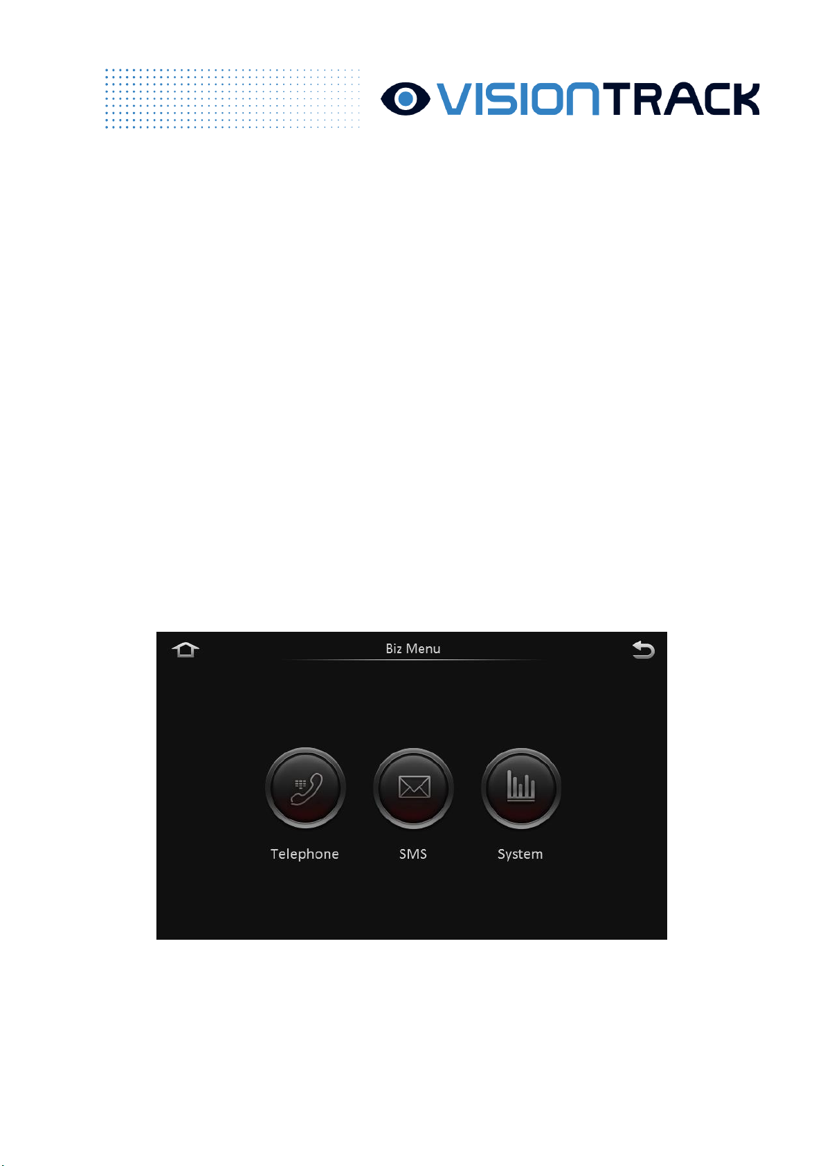
2.1 Business Menu
Click “Business Menu”and the following screen is displayed. The user doesn’t need to enter the
password to go into Business Menu and common users and drivers all have access to it.

2.1.1 Dial Function
The device supports the user to dial. The Dial screen is shown as follows:
Contacts/Records:
⚫Records of Contacts can only send telephone numbers via the 808 platform. Saving
telephone numbers on the device is not allowed.
⚫Like the cellphone, Records all call records, including: received calls, missed callas and
dialed calls.
2.1.2 Short Message
Short message is divided into read mailbox and unread mailbox
⚫Short message can only be sent by the business platform.
2.2 User Login
Click “Login”on the preview screen and the user needs to select his username and enter the
password to log in.

⚫Username (admin or user) cannot be manually entered. It can only be selected by the
drop-down box. User management is conducted in User Settings of Parameter Settings.
⚫The user can enter the parameter settings menu after the login. If the user directly clicks
“Return”to go back to the preview screen, then he doesn’t need to re-enter the username and
password the next time he enters the settings screen.
⚫If the user clicks “Logout”, then he needs to re-enter the username and password the
next time he enters the settings screen.
3 Main Functions
3.1 Basic Functions
3.1.1 Recording Search
Click REC search to enter the recording search screen. The user can search primary/sub-stream
recording at a certain date according to his needs. Different colors indicate various types of recording

of the day.
⚫Calender search. Recording types available include main recording, sub-recording and
mirror recording.
⚫Recording search depends on recording types instead of the storage way. Recording is
classified as: all, alarm recording and regular recording.
⚫To select all, search eligible channels; to select alarm recording, only search alarm
linkage recording; to select regular recording, search all recording other than alarm recording.

⚫Click “-”or “+”above the timeline to zoom in and out the time range. The function is
especially useful when there are many video segments or the user intends to play back the video
from a certain time range.
⚫Click Up and Down arrow on the right to view the recording of every channel, like
whether there is recording and the recording within each time period. Green means regular
recording, red indicates unlocked alarm recording and yellow means locked alarm recording.
3.1.2 Export Recording
⚫To export recording, the user can select time period, drag the timeline or directly enter
the time. Then, he can click “Start time”to set the start time for export and switch to end time
set by the following photo.
⚫Click “End time”to confirm the time period for export and the size of exported files.
⚫Click “Export recording”and select the format to export recording.
⚫Integrated data: package and export original H.264 data stream and black box data. The
exported integrated data can only be played by the player (platform) provided by Streamax.
Black box data will be linked with video data when playing the video.
⚫AVI data: namely the standard AVI format. It can be played by any player.

3.1.3 Log Search
Click Log Search to enter the log search screen.
⚫Click “Next”:
⚫Log can be searched according to time periods.
⚫Log is classified as: operation log, alarm log, locked log and P2 operation log.
⚫When selecting the alarm log, if the log has recording to link with, then the Play button
corresponding to the log can be selected. Otherwise, it is not optional.
⚫The user can directly play back and export the alarm log with video.
Tabla de contenidos
Otros manuales de Cámara de salpicadero de VisionTrack


