Viessmann Vitoclima 200-C Instrucciones de funcionamiento

VIESMANN
Service instructions
for contractors
Vitoclima 200-C
Chillers for external installation as 400 V version
For cooling as well as for cooling and heating operation
For applicability, see the last page
VITOCLIMA 200-C
5692 696 GB 2/2007 Please keep safe.

Please follow these safety instructions closely to prevent accidents and
material losses.
Safety instructions explained
Danger
This symbol warns against the
risk of injury.
!Please note
This symbol warns against the
risk of material losses and
environmental pollution.
Note
Details identified by the word "Note"
contain additional information.
Target group
These instructions are exclusively
designed for qualified personnel.
&Work on the refrigeration circuit
must only be carried out by qualified
and authorised refrigeration engi-
neers.
&Work on electrical equipment must
only be carried out by a qualified
electrician.
&The system must be commissioned
by the system installer or a qualified
person authorised by the installer.
Regulations
Observe the following when working
on this system
&all legal instructions regarding the
prevention of accidents,
&all legal instructions regarding
environmental protection,
&the Code of Practice of relevant
trade associations.
&all current safety regulations as
defined by DIN, EN, VDE and all
locally applicable standards
Working on the system
&Isolate the system from the power
supply and check that it is no longer
'live', e.g. by removing a separate
fuse or by means of a main isolator.
&Danger
Contact with 'live' compo-
nents can lead to severe inju-
ries. Some components on
the PCBs will remain 'live'
even after the power supply
has been switched OFF.
&Prior to removing equipment
covers wait at least 4 min. to
allow the voltage to dissi-
pate.
&Safeguard the system against
unauthorised reconnection.
!Please note
Electronic modules can be
damaged by electrostatic dis-
charges.
Touch earthed objects, such as
heating or water pipes, to dis-
charge static loads.
Safety instructions
2
Safety instructions
5692 696 GB

Repair work
!Please note
Repairing components that ful-
fil a safety function can com-
promise the safe operation of
your system.
Replace faulty components
only with original Viessmann
spare parts.
Ancillary components, spare and
wearing parts
!Please note
Spare and wearing parts that
have not been tested together
with the heating system can
compromise its function. Instal-
ling non-authorised compo-
nents and non-approved
modifications or conversions
can compromise safety and
may invalidate our warranty.
For replacements, use only ori-
ginal spare parts supplied or
approved by Viessmann.
Safety instructions (cont.)
3
Safety instructions
5692 696 GB

Unit layouts
Unit layout type OC208 ............................................................................... 6
Unit layout type OC211 to OC215................................................................ 8
Connection and wiring diagrams ................................................................. 9
Commissioning, inspection, maintenance
Steps - commissioning, inspection and maintenance ................................... 10
Further details regarding the individual steps .............................................. 12
Troubleshooting
Control unit diagnostics .............................................................................. 27
Diagnosis ................................................................................................... 30
Control settings
Menu structure overview ............................................................................. 33
Scanning and changing parameters ............................................................ 35
Code entry.................................................................................................. 35
Selecting the set value for heating mode (HEA) ........................................... 36
Selecting the set value for cooling mode (Coo) ............................................ 37
Scanning sensor values.............................................................................. 37
Components
Phase monitor ............................................................................................ 39
Differential pressure regulator..................................................................... 39
Refrigerant circuits
Units for cooling mode ................................................................................ 40
Units for heating or cooling operation .......................................................... 42
Parts lists
Parts list Vitoclima 200-C, type OC208........................................................ 44
Parts list Vitoclima 200-C, type OC211 to OC215 ........................................ 44
Parts list fan convectors, type V202H to V209H........................................... 45
Parts list ceiling cassette devices, type C202H to C205H ............................ 45
Parts list duct mounted devices, type DC205H to DC210H........................... 45
Commissioning/service reports
Test report .................................................................................................. 46
Specification (units for cooling and heating mode)................................. 48
Specification (units for cooling mode)..................................................... 51
Index
4
Index
5692 696 GB

Appendix
Pump curves .............................................................................................. 53
Certificates
Declaration of conformity ............................................................................ 57
Keyword index .......................................................................................... 58
Index (cont.)
5
Index
5692 696 GB

AManual air vent valve on the flow
BON/OFF switch
CProgramming unit
DCover for the circulation pump
EPhase monitor (only for 400 V ver-
sion)
FDiaphragm expansion vessel
GFill & drain valve
Unit layout type OC208
6
Unit layouts
5692 696 GB
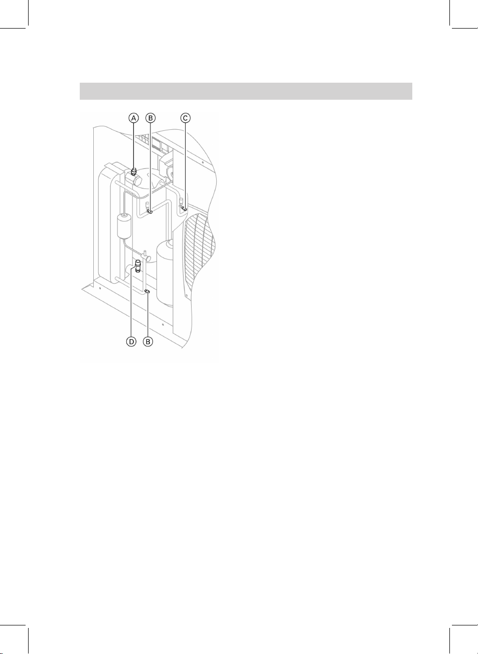
AManual air vent valve
BService valves, low pressure side
CService valve, high pressure side
DSafety valve, hydraulic circuit
Unit layout type OC208 (cont.)
7
Unit layouts
5692 696 GB

AON/OFF switch
BProgramming unit
CPhase monitor (only for 400 V ver-
sion)
DAutomatic air vent valve
EDiaphragm expansion vessel
FFill & drain valve
GService valve, low pressure side
HService valve, high pressure side
Unit layout type OC211 to OC215
8
Unit layouts
5692 696 GB

Rear view with back panel removed
ACover for the circulation pump
BSafety valve, hydraulic circuit
Connection and wiring diagrams
The connection and wiring diagrams
are affixed to the inside of the front
panel.
Unit layout type OC211 to OC215 (cont.)
9
Unit layouts
5692 696 GB

For further information regarding the individual steps, see the page indicated
Commissioning steps
Inspection steps
Maintenance steps Page
!!!
••• 01. Switching OFF the main fuse/MCB and the system
ON/OFF switch ....................................................................... 12
••• 02. Checking the refrigerant circuit for leaks.................... 12
•03. Filling the system.................................................................. 12
••• 04. Checking the diaphragm expansion vessel and the
pressure of the hydraulic circuit..................................... 13
• • 05. Cleaning the water filter ..................................................... 14
•06. Cleaning the condensate drain........................................ 15
••• 07. Checking the free rotation of the fans........................... 15
•08. Cleaning the air heat exchanger...................................... 15
••• 09. Checking the function of the safety valve
• • 10. Checking the tightness of electrical connections . . . . 16
••• 11. Switching ON/connecting the main fuse
••• 12. Switching the system ON/OFF switch ON (if
installed)
•13. Placing the unit in standby mode ................................... 17
••• 14. Ensuring that load is drawn .............................................. 17
••• 15. Switching the unit ON.......................................................... 17
•16. Adjusting parameters HEA and H31 .............................. 18
•17. Adjusting the throughput in the hydraulic circuit . . . . 18
• • 18. Checking the set values and adjusting, if required. . 21
•19. Checking the superheating and correcting, if
required (cooling mode) ..................................................... 22
•20. Checking the evaporator parameters............................ 23
•21. Checking the high pressure switch ............................... 23
•22. Checking the low pressure switch ................................. 23
Steps - commissioning, inspection and maintenance
10
Commissioning, inspection, maintenance
5692 696 GB
Otros manuales para Vitoclima 200-C
1
Este manual sirve para los siguientes modelos
6
Tabla de contenidos
Otros manuales de Enfriador de Viessmann


