VEXILAR FL-10 Manual de usuario

1
CONTENTS
General Description 2
Specifications 3
Unit Installation 4 - 5
Transducer Installation 6 - 9
Unit Operation 10 - 15
elpful Tips 16
Trouble Shooting Chart 17
About Transducer Beam Angles 18 - 19
Other Vexilar Products 20 - 21
Transducers 22 - 22
Service and Support 24
Founded in 1960, Vexilar, Inc. has a
long history of bringing revolutionary
technology to the sport fishing industry.
Just some of the Vexilar firsts include: the
first liquid crystal display, the first fish
alarm, the first three color display, and
the first CRT and straight line paper
graphs for the sport fisherman.
FL-10 Operation Manual

2
GENERAL DESCRIPTION
The FL-10 is a
compact in-dash
mounted flasher
fish finder. Besides
indicating depth,
the unit also shows
changes in bottom
content and condi-
tions. It can also
discriminate
between large underwater targets, such as fish, and smaller
targets like baitfish and plankton.
The unit transmits bursts of high frequency pulses, which
are converted from electrical to mechanical energy by the
transducer. These "sound" pulses radiate from the
transducer downward and are reflected back up to the
transducer where the energy is converted back to electrical
signals. The FL-10 then processes these signals and displays
them.
The circular display is accomplished by attaching an LED
(Light Emitting Diode) to a wheel, which is then spun at a
high speed in the clockwise direction. This allows for an
extremely high speed update. The bottom, as well as other
targets, are displayed as red, orange, or green to indicate
strong, medium and weak signals respectively.
3
SPECIFICATIONS
Operating Voltage: 10.5 - 15 Volts (12 Volts Nominal)
Current Draw: .25 Amps
Power Output: 400 Watts (Peak to Peak)
Frequency: 200 k z
Resolution: 525 Segments
Target Separation: 2.65" Min.
Display Colors: 3 - Red, Orange, and Green
Depth Scales: 0-20, 0-40, and 0-200’ Feet
Weight: 2-1/2 Lbs. w/transducer
Tran ducer Beam Angle:
Puck Style - 12 Degree
Transom Mount - 12
Degree
Additional beam angle
options are available.
See page 22
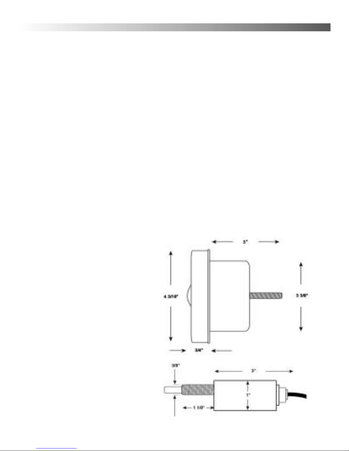
Dimen ion
The FL-10 is designed to
fit in a 3-3/8” to 3 1/2”
hole.

4
UNIT INSTALLATION
To install the unit refer to Figure 4. You must have a
minimum 3-3/8" hole in your dash or panel. Also, within 12",
you should dedicate space for a 3/8" hole for the control and
decal. Make sure that you will have enough room behind the
dash to accept the unit and control. The flasher unit and the
control each needs at least 3" of depth.
To mount the flasher unit, feed the transducer, power, and
control cables through the larger hole and set the unit into
place. From behind the panel, place the metal U bracket onto
the back of the unit so that the arms of the bracket will make
contact with a solid part of the backside of the panel. Make
sure the Zero Mark on the flasher display is at the 12 o’clock
position and then use the provided wing nut to tighten the
unit into place. If the stud protruding from the back of the
flasher is not long enough you can reduce the length of the
bracket arms using the marks to guide you. Use a pair of
pliers to snap off a section of each arm at the pre-cut
perforations.
Before you mount the control unit, first install the control
decal. Remove the peel-off backing and carefully place the
decal over the hole making sure that the hole in the decal
aligns with the hole in the dash and that the decal is straight
and level before you press it into place. Next, install a nut,
star washer onto the control shaft. Insert the control unit from
behind the panel into the 3/8" hole. Install the remaining nut
and star washer onto the shaft from the front side. The posi-
tion of the nuts will be determined by the thickness of the

panel. Ideally you want the outside nut to be as close to the
outer end of the shaft as possible. When the right spacing has
been achieved tighten snugly into place.
Make sure the inner shaft portion is rotated fully
counter-clockwise and then place the larger rubber o-ring fol-
lowed by the larger control knob onto the shaft. Using the
provided wrench, tighten the knob down. Make sure that the
white mark lines up with the OFF position on the decal. Next
install small rubber o-ring and then the smaller control knob.
Make sure that, with the shaft turned fully counter-clock-
wise, the white mark lines up with the minimum position.
Finally, plug the eight pin connector from the flasher unit into
the back of the control and tighten snugly.
Connect the power cable to a 12 volt source. It is
recommended to use the main starting battery for power.
Connect the white wire to positive and the black to negative.
5
Figure 4

6
PUCK TRANSDUCER MOUNTING
To attach a puck style transducer
to a trolling motor use the large cable
tie provided. Notice the slots in the
transducer for this purpose. Locate the
transducer on the bottom of the lower
unit (figure 5). Run the cable up the
shaft using smaller cable ties to hold
it in position. Make sure that the
motions of the trolling motor will not
damage the cable. Before you plug the
transducer connector into the inline
jack, it is recommended to spray some
lubricant or dab some common petroleum jelly inside. This
will help prevent long term corrosion.
IN-HULL MOUNTING
Puck transducers can also be mounted in-hull. This
method gives high-speed readings without the worry of
having a transducer hanging on the back of the boat to get
damaged. Finding the best location for the transducer before
installation is critical. Choose a flat smooth spot near the
center of the transom of the boat near the drain plug area. It
is recommended to make a "test run" before you permanently
install the transducer to make sure that you can get a good
reading through your hull at all speeds. You may need
someone’s help for the test, but it will insure you get a good
reading after final installation.
Figure 5

7
After the boat is launched, put about a half inch of water
in the bilge and set the transducer into the the water. Moving
it even an inch in any direction can effect the quality of the
reading drastically. Move it around until you get the best
reading. Be sure to try this when the boat is on plane and
running at top speed. Mark the best spot.
To install the transducer, first clean the spot of mud and
oil and then dry it thoroughly. Using an epoxy* or silicone
glue, make a puddle, about the same size as the transducer,
on the inside of the hull. Place the transducer in the glue and
press it down firmly, gently twisting it back and forth,
making sure that there are no air bubbles in the glue between
the transducer and the hull. It is important that you let the
glue dry completely before turning the unit on.
Run the transducer cord up to the unit. Before you plug
the transducer connector into the inline jack, it is
recommended to spray some lubricant or dab some common
petroleum jelly inside. This will help prevent long term
corrosion.
* If your hull is aluminum, use silicone. This material will flex with
the hull at high speeds and in rough water.

8
TRANSOM TRANSDUCER MOUNTING
Locate the transducer, and bracket hardware. This
includes;
1 - Transducer
2 - Angle Brackets
4 - Bracket Screws
2 - Bracket Plates
4 - Nuts
4 - Mounting Screws
First, attach the bracket to the transducer as shown in
Figure 7. The flanges of the bracket normally point outward,
away from the transducer. If mounting space is tight, you can
reverse the angle brackets and face the flanges inward.
TRANSOM TRANSDUCER INSTALLATION
When choosing an area to mount the transducer, keep in
mind that you need smooth water flow across the face of the
transducer to insure a good reading at all speeds. Try to stay
away from rivets, ribs, or strakes that would be just in front
of the transducer. They can disturb the water and scramble
the reading.
With the mounting bracket attached to the transducer,
hold it up to the boat where you are planning to mount it.
Mark the holes on the transom, or mounting plate, so the
bottom of the transducer is flush with the bottom of the boat
the holes are located at the bottom of the bracket slots. This
gives you room to "fine tune" the position of the transducer
and optimize your reading after you've put the boat in the

9
water. Ideally, the
transducer should be just
under the bottom of the
boat. owever, you may
need to lower it 1/2” to
5/8”, depending on your
hull shape, to get a good
reading at top speed.
Drill out the holes and
tighten the bracket to the
hull securely. Be sure to
seal any holes drilled into
the transom with silicone
to prevent water from
leaking into the boat. Give
the rear of the transducer
a slight tilt downward so
that the back is about 1/8”
lower than the front.
Tighten the bracket screws and nuts securely. Run the trans-
ducer cord up to the unit. Before you plug the transducer
connector into the inline jack, it is recommended to spray
some lubricant or dab some common petroleum jelly inside.
This will help prevent long term corrosion.
Figure 7

10
UNIT OPERATION
To switch the FL-10 on, turn the larger control knob to the
right. Turning the unit on also selects the depth range. The
first setting covers zero to 20 feet. The second range covers 0
to 40 feet and the third range covers 0 to 200 feet. If the first
setting shows only a mark at the zero position on the display,
switch to a deeper range until you see the depth mark appear.
Depth is read in the clockwise direction. Zero, or the water
surface, is at the 12:00 position. The depth gets deeper as you
go around the dial clockwise.
GAIN CONTROL
The smaller knob is the gain control. This controls the
amount of signal that you see on the display. A gain setting
of MIN will display a minimum amount of signal while a
gain setting of MAX will show the maximum amount.
Different conditions will require different gain settings. Deeper
water will require higher gain than shallow water. A weedy
bottom will demand a lower gain setting than a clean bot-
tom. Keep the gain level low. Too much gain can "wash out"
the targets that you want to see. Generally, it is a good idea
to set the gain at an appropriate level and leave it there, unless
water depth or conditions change substantially.
Otros manuales para FL-10
1
Tabla de contenidos
Otros manuales de Buscador de peces de VEXILAR


