Verano SCREEN V585 Manual de usuario
INSTALLATION MANUAL
SCREENS
V585 - V595

INSTALLATION MANUAL SCREENS
1787-190826EN
1
Subject to misprints, errors and technical modifications.
Important BEFORE mounting
Please be aware of damages
Do not use a knife or any other sharp object while opening the packaging. The product could get damaged. Place the
product on a so surface. Please take care while drilling. Drilling waste may cause damages.
Check if the frame or facade is completely at.
General warning
Installation of this product is at your own risk. Use this mounting instruction only as an assistance and only with the
mounting of this specic product. If you can not install this product yourself, you can always opt for professional
installation. Your dealer’s installation team is always ready to assist you.
Index
page
Content package 2
Required tools 2
Specications screen 3
Specications guiding rail 4
1. Mounting (L)HTF-guiding rail 5
1.1 Drawing mounting holes 5
1.2 Drilling mounting holes in guiding rail 6
1.3 Mounting guiding rail 7
2. Mounting (L)HTF + CLICK guiding rail 8
2.1 Mounting click cubes 8
2.2 Mounting guiding rail 8
2.3 Mounting (L)HTF + CLICK guiding rail without click cubes 8
3. Hole control 9
4. Installing screenbox on to guiding rails 9
5. Finishing mounting outside 10
6. Instruction installing manually controlled (inside) 11
7. Instruction installing electrically controlled (inside) 13

INSTALLATION MANUAL SCREENS
1787-190826EN
2
Subject to misprints, errors and technical modifications.
Content
1. Screen including screenfabric, operating type, bottom rail and operating box
a. Manually: cord or strap
b. Electrically: switch + plug
c. Remote control: remote control + plug
2. Guiding rails (with spacers or clicking cubes)
3. Covering caps
4. Sealing caps
Required tools
• Drilling machine
• Metal drill 6/10/20 mm
• Masonry drill 6/10/20 mm
• Head screwdriver
• Tapeline
• Plumb rule
• Pencil
In case of electrically controlled:
• Nippers
• Flathead screwdriver
1
2
3
4

INSTALLATION MANUAL SCREENS
1787-190826EN
3
Subject to misprints, errors and technical modifications.
95
95 85
85
17
26
17
26
Specications screenbox
Screen V585
beveled straight
Screen V595
beveled straight
Section box
Section box
Sizes in mm
95
95 85
85
17
26
17
26

INSTALLATION MANUAL SCREENS
1787-190826EN
4
Subject to misprints, errors and technical modifications.
Specications guiding rail
LHTF LHTF + LIP LIP
Sizes in mm
Section HTF guiding rail le
Section LHTF guiding rail le
Section HTF + CLICK guiding rail le Section HTF + CLICK + lip guiding rail le
Section LHTF + lip guiding rail le
HTF HTF + CLICK HTF + CLICK + LIP
The extra lip on to the guiding rail
gives the fabric extra protection
against the clacking of the fabric.
INSTALLATION MANUAL SCREENS
1787-190826EN
5
Subject to misprints, errors and technical modifications.
> 15 cm
Y
± 50 cm
> 2 cm
± 50 cm
in de dag, LHTF geleider
op de dag, HTF geleider in de dag, HTF geleider
Y = height guiding rail
Screws per guiding rail
Y < 125 cm : 2x
Y = 125-225 cm : 3x
Y > 225-285 cm : 4x
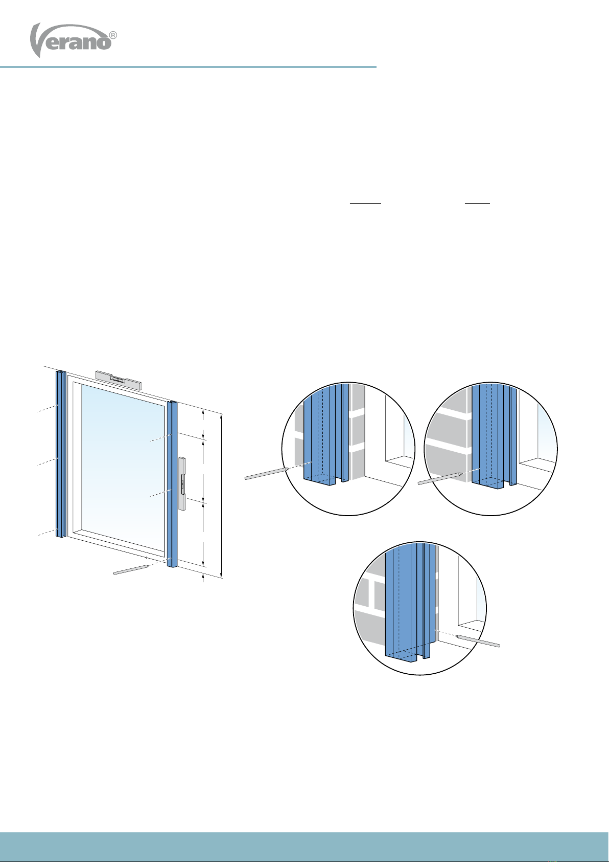
1.1 Drawing mounting holes
The guiding rails are not drilled yet. The number of holes and the placement of the holes depends on the surface and size
of the screen. The surface can be wooden, metal or concrete.
1. Place the le guiding rail vertically, at the right height, against the frame or facade. See gure 1.1.
2. Draw the mounting holes on the guiding rail. Your choice of mounting, ‘outside’ (on to the wall) or ‘inside’ (in the window
frame), determines how the guiding rail is mounted. When mounted ‘outside’, you should ensure the mounting holes are
in the middle of a stone, not in the joint! The rst hole at the point of attachment to the screen box, should be drilled at
least 15 cm from the edge. This space must be kept free for the top bracket. The bottom hole must be at least 2cm from
the bottom.
3. Then place the right guiding rail to the correct height and width against the frame or the facade and mark the mounting
holes in the same way.
Be aware! The le and right guiding rail must be exactly level. Use a plank and plumb rule to check this.
1 Mounting (L)HTF-guiding rails
Fig. 1.1 Drawing mounting holes
Outside mount, HTF guiding rail Inside mount, HTF guiding rail
Inside mount, LHTF guiding rail

INSTALLATION MANUAL SCREENS
1787-190826EN
6
Subject to misprints, errors and technical modifications.
Y Y
HTF geleider LHTF geleider
6 mm 6 mm10 mm
> 15 cm > 15 cm
> 2 cm > 2 cm
1.2 Drilling mounting holes in guiding rail
HTF guiding rail: First drill a hole of 6mm through both layers of the guiding rail. Then drill the top hole with a 10 mm
drill so that the screw ts through it. The plastic covering caps will be placed in these holes later on.
LHTF guiding rail: Drill all holes with a 6mm drill.
Fig. 1.2 Drilling mounting holes
HFT guiding rail LHFT guiding rail

INSTALLATION MANUAL SCREENS
1787-190826EN
7
Subject to misprints, errors and technical modifications.
HTF geleider
afstandsbusje
LHTF geleider
HTF geleider
afstandsbusje
LHTF geleider
in de dag, LHTF geleider
Fig. 1.3 Mounting guiding rail Fig. 1.4 Beveled windowsill
1.3 Mounting guiding rail
1. Place the guiding rails against the wall or window frame. Make sure the guiding rails are perpendicular and are level
with the wall or window frame. Based on the holes in the guiding rails you can now mark the drilling holes.
2. Drill the nal holes. Keep in mind the size of the screws and plugs you will be using.
3. When mounting ‘outside’(onto the wall): Screw the guiding rails.
When mounting ‘inside’ (in the window frame): First make the hole for the control and place the screen box on to
the guiding rails before mounting the guiding rails. (see instruction
3 ‘hole control and 4 ‘installing screenbox on to guiding rails’)
Be aware!
When mounting the HTF guiding rail you should place a
lling tube at each mounting hole between the guiding
rail and the wall or window frame.
Be aware with beveled windowsill!
Have you got a beveled windowsill? First saw the
LHTF guiding rail in the same angle as the angle of your
windowsill. This is only necessary for ‘inside’ mounting
(mounting in the window frame or between two walls).
Be aware!
When a screen must be mounted in the window frame or
under low eaves or gutter, it is necessary to put the top box on
to the guiding rails before the guiding rails are screwed to the
wall.
Be extra careful with the mounting. The brackets are very
fragile! To prevent the brackets from breaking, you should
always li the screen with two persons at the guiding rail
attachment point with the box.
Fig. 1.5 Mounting under low eaves
HFT guiding rail
LHFT guiding rail
Filling tube

INSTALLATION MANUAL SCREENS
1787-190826EN
8
Subject to misprints, errors and technical modifications.
HTF + KLIK geleider
HTF + KLIK geleider (zonder klikblokje)
klikblokje
HTF + KLIK geleider
HTF + KLIK geleider (zonder klikblokje)
klikblokje
2.2 Mounting guiding rail
1. Click the guiding rails on to the cubes.
2. Check if the guiding rails are perpendicular and are level with the wall or window frame.
2 Mounting (L)HTF + CLICK guiding rail
2.1 Mounting click cubes
1. Place the guiding rail vertically, at the correct width
and height, against the wall or the window frame and
determine the exact position of the click cubes.
2. Mount the top click cube all the way at the top of the
guiding rail. The top box will eventually rest on this.
When mounted on to a wall, you should ensure the mounting
holes are in the middle of a stone, not in the joint!
Be aware!
Make sure the click cubes are level, both horizontally as
vertically. Use a plank and plumb rule to check this.
2.3 Mounting (L)HTF + CLICK guiding rail without click cubes
It is also possible to mount the HTF + CLICK guiding rail without the click cubes. The guiding rails are mounted directly to
the wall or window frame, in the same way as the HTF guiding rail.
For mounting follow the instructions on page 5 up to 7 ‘Mounting (L)HTF guiding rail’.
Y
Fig. 2.1 Mounting click cubes
Fig. 2.2 Mounting HTF + CLICK with click cubes
Fig. 2.3 Mounting HTF + CLICK guiding rail without click cubes
Y = guiding rail height
Click cube

INSTALLATION MANUAL SCREENS
1787-190826EN
9
Subject to misprints, errors and technical modifications.
3 Hole for control
1. Accurately draw a hole on the wall where the (electrical) cord/strap should go through for operation. This hole is exactly
on the same heigth as where the (electrical) cord/strap comes out of the screenbox.
2. Drill the hole in the wall.
Hole for strap operated: 20mm (drill 10mm from outside, then drill the hole from the inside to the outside with
a 20mm drill).
Hole for cord operated: 12mm (place the included spring in the hole).
Hole for electrical cord: 10mm
Please note! Check carefully if there are no pipes etc. in the wall when drilling the hole. Always use a board when
drilling on the inside of the house. This will prevent the stucco from damaging.
1
elektrische snoer
of koord band
2
4 Installing screenbox on to guiding rails
1. Li the box with 2 persons.
2. Guide the (electrical) cord/strap inside through the drilled hole. Make sure the strap is not twisted.
3. Slide the boxbrackets, which protrude under the box, into the guiding rails. Please be extra careful during this process.
The boxbrackets are very vulnerable!
4. Check if the box is completely level.
5. The box rests onto the guiding rails. The box sits rmly enough and does not need to be secured.
Fig. 4.1 Installing top box
Electrical (cord) Strap
Otros manuales para SCREEN V585
1
Este manual sirve para los siguientes modelos
1
Tabla de contenidos
Otros manuales de Pantalla de proyección de Verano


