Vent-Axia Solo Pro SVP Instrucciones de montaje

SELV RANGE
Installation and Wiring Instructions
Stock Ref. N°
Solo Pro SVP 409163
Solo Pro SVT 409164
Solo Pro SVHTP 409165
PLEASE READ INSTRUCTIONS IN CONJUNCTION WITH ILLUSTRATIONS.
PLEASE SAVE THESE INSTRUCTIONS.
Solo Pro
IPX7
FAN UNITS 12V 50Hz SELV (CLASS III)
CONTROLLERS 220-240V 50Hz MAINS SUPPLY (CLASS II)
WITH 12V 50Hz SELV OUTPUT

2

3
Installation and Wiring Instructions for the Solo Pro SELV Fans and Controllers.
IMPORTANT:
READ THESE INSTRUCTIONS
BEFORE COMMENCING THE
INSTALLATION
DO NOT install this product in areas where the following may be present or occur:
•Excessive oil or a grease laden atmosphere.
•Corrosive or flammable gases, liquids or vapours.
• Ambient temperatures higher than 40°C or less than –5°C.
• Possible obstructions which would hinder the access or removal of the Fan.
SAFETY AND GUIDANCE NOTES
A. All wiring to be in accordance with the current I.E.E. Regulations, or the appropriate
standards of your country and MUST be installed by a suitably qualified person.
B. The Fan should be provided with a local isolator switch capable of disconnecting all poles,
having a contact separation of at least 3mm.
C. Ensure that the mains supply (Voltage, Frequency, and Phase) complies with the rating
label.
D. The Fan should only be used in conjunction with the appropriate Vent-Axia products.
E. The fan should only be used in conjunction with fixed wiring.
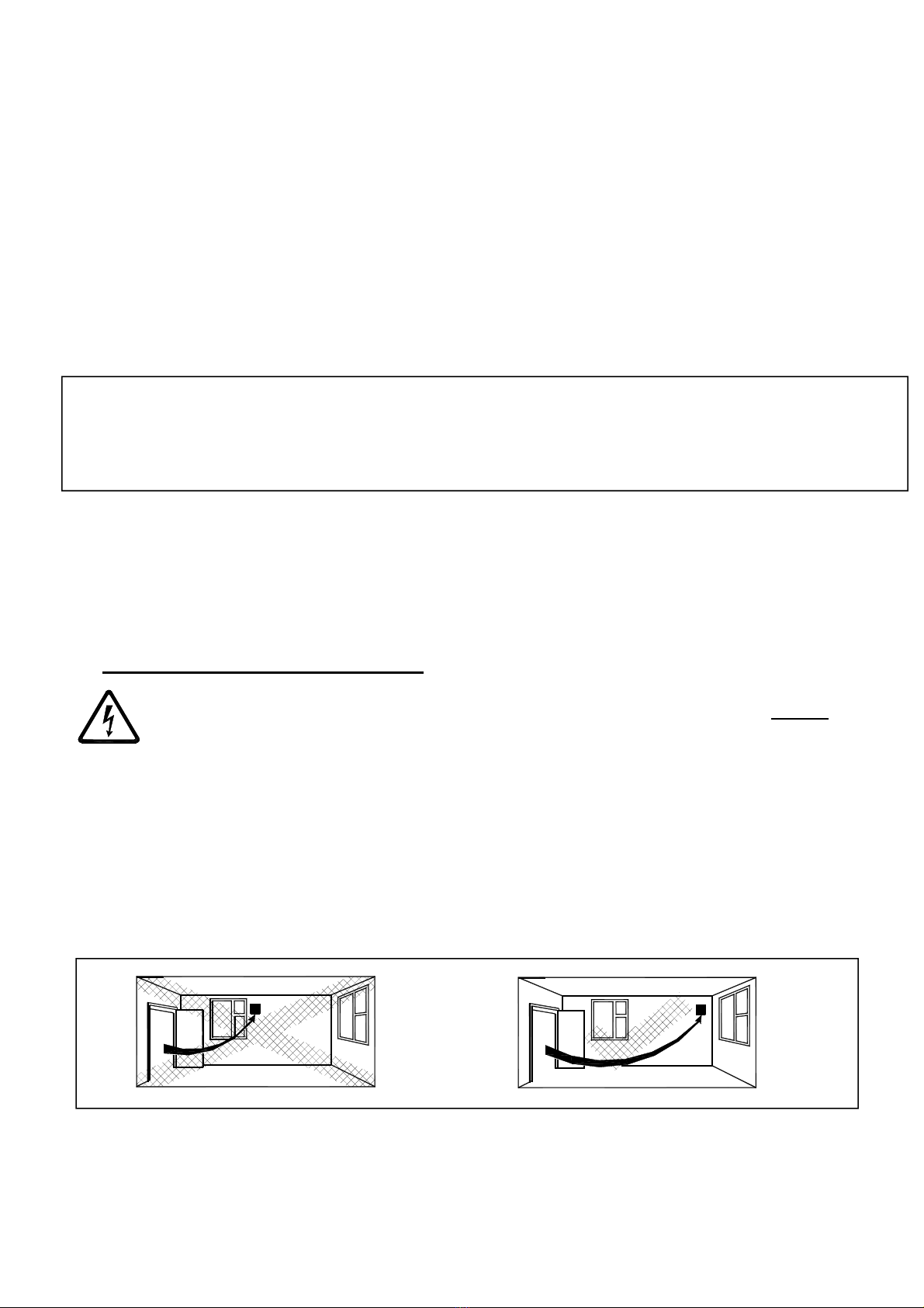
F. When the Fan is used to remove air from a room containing a fuel-burning appliance,
ensure that the air replacement is adequate for both the fan and the fuel-burning appliance.
G. The Fan should not be used where it is liable to be subject to direct water spray for
prolonged periods of time.
H. Where ducted Fans are used to handle moisture-laden air, a condensation trap should be
fitted. Horizontal ducts should be arranged to slope slightly downwards away from the Fan.
I. This appliance is not intended for use by persons (including children) with reduced physical,
sensory or mental capabilities, or lack of experience and knowledge, unless they have been
given supervision or instruction concerning use of the appliance by a person responsible for
their safety.
J. Young children should be supervised to ensure that they do not play with the appliance.
IMPORTANT:- ONLY CONNECT TOGETHER PRODUCTS FROM THE SOLO PRO
SELV RANGE SINCE THE FANS ARE SPECIALLY DESIGNED TO WORK ON 12V
AC AND ARE NOT COMPATIBLE WITH OTHER VENT-AXIA CONTROLLERS. DO
NOT CONNECT MORE THAN ONE FAN TO THE CONTROLLER.
DESCRIPTION
The Solo Pro SELV fan is an extract fan for bathrooms and toilets specifically designed
for ducted applications. Pullcord, Timer, and Humidity options are available.
ACCESSORIES (not supplied)
WALL FITTING KIT
A range of white (stock ref. 254102) or brown (stock ref. 254100) 100mm wall kits are
available for installing into most walls using telescopic liners supplied.
WINDOW FITTING KIT

4
A window fitting kit is available. Stock reference 11461685.
A. INSTALLATION
SITING THE CONTROLLER
1. The controller must not be installed in a shower cubicle or enclosure. It must be
sited away from direct sources of water spray and out of reach (1.5m) of a person
using a fixed bath or shower.
2. Site away from direct sources of heat. Ambient temperature range 0 to 40ºC. Do
not site in an area containing excessive levels of grease.
3. Decide where to site the controller and fan (see section siting the fan), and work
out the required cable runs.
PANEL/CEILING MOUNTING – (FIG.4.)
1. Cut a 105mm diameter hole.
2. Remove the front panel by carefully pulling it away from the fan.
3. Loosen the two self-retaining screws and remove the inner cover by carefully
pulling it away from the housing.
4. Remove the impeller by carefully pushing the retaining clips together.
5. Remove the PCB cover by loosening the two screws and pulling it out of the fan
housing.
6. Mark the screw centres through the holes in the fan back plate. Drill, plug and
screw into position. Attach ducting and back draught shutters as required for the
installation.
7. Wire the fan as described in Section B-Wiring. Adjust any settings as required
(see Section C-Setup).
8. Replace the PCB and inner covers and tighten the retaining screws.
9. After installation, ensure impeller rotates freely. Replace the front panel.
WALL MOUNTING – (FIG.4.)
1. For wall mounting cut a 117mm diameter hole through the wall and insert the wall
sleeve. Slope the sleeve slightly downwards away from the fan. Where necessary
cut to length and cement both ends into position flush with the wall faces.
2. Fix exterior grille into position with the louvres positioned downwards.
3. Remove the front panel by carefully pulling it away from the fan.
4. Loosen the two self-retaining screws and remove the inner cover by carefully
pulling it away from the housing.
5. Remove the impeller by carefully pushing the retaining clips together.
6. Remove the PCB cover by loosening the two screws and pulling it out of the fan
housing.
7. Mark the screw centres through the holes in the fan back plate. Drill, plug and
screw into position. Attach ducting and back draught shutters as required for the
installation.
8. Wire the fan as described in Section B-Wiring. Adjust any settings as required
(see Section C-Setup).
9. Replace the PCB and inner covers and tighten the retaining screws.
10. After installation, ensure impeller rotates freely. Replace the front panel.

5
B. WIRING.
WARNING: THE FAN AND ANCILLARY CONTROL EQUIPMENT MUST BE
ISOLATED FROM THE POWER SUPPLY DURING THE INSTALLATION /
OR MAINTENANCE.
IMPORTANT: The controller is only suitable for connection to a 220-240V 50Hz AC
single phase mains electrical supply. It is double insulated (CLASS II)
and therefore must not be earthed. It provides a 12V 50Hz AC Safety
Extra Low Voltage for the Solo Pro SELV range of fans. Note that
only one fan must be connected to the controller.
1.5mm² wire is recommended for cable runs up to 8m.
1. Select and follow the appropriate wiring diagram. (Fig. 1, 2 or 3)
2. Check all connections have been made correctly and ensure all terminal
connections and supply wires are securely fastened.
3. Ensure the impeller rotates and is free from obstructions once reassembled (Fig. 4
and 5).
C. SETUP
WARNING: THE FAN AND ANCILLARY CONTROL EQUIPMENT MUST BE
ISOLATED FROM THE POWER SUPPLY DURING THE INSTALLATION /
OR MAINTENANCE.
Timer adjustment (SVT)
BEFORE ADJUSTING THE TIMER, SWITCH OFF THE MAINS SUPPLY. TIMER
SHOULD ONLY BE ADJUSTED BEFORE OR DURING INSTALLATION.
1. Unscrew the fixing screws on the cover of the controller. The fan overrun period
can be adjusted up or down using the pot located on the internal PCB.
2. To REDUCE the operating time, use a small screwdriver to turn the pot ANTI-
CLOCKWISE.
3. To INCREASE the operating time, use a small screwdriver to turn the pot
CLOCKWISE.
4. Replace the controller cover.
TIMER ADJUSTMENT (SVHTP, FIG. 4 AND 5)
BEFORE ADJUSTING THE TIMER, SWITCH OFF THE MAINS SUPPLY. TIMER SHOULD
ONLY BE ADJUSTED BEFORE OR DURING INSTALLATION.
1. Remove the fan and PCB covers and the impeller (Fig. 4 and 5). The controller is
factory set at 15 minutes approx. The overrun period can be adjusted from 3-25
minutes by altering the pot on the control PCB.
2. To REDUCE the operating time, use a small screwdriver to turn the pot ANTI-
CLOCKWISE.
3. To INCREASE the operating time, use a small screwdriver to turn the pot
CLOCKWISE.
4. Replace the fan and PCB covers and the impeller.

6
HUMIDITY SET-POINT ADJUSTMENT (FIG. 4 AND 5)
BEFORE ADJUSTING THE CONTROLLER, SWITCH OFF THE MAINS SUPPLY.
HUMIDISTAT SHOULD ONLY BE ADJUSTED BEFORE OR DURING INSTALLATION.
1. Remove the fan and PCB covers and impeller. The controller is factory set to
switch on at about 70% RH. The humidity set point can be adjusted from 40-
95%RH by altering the adjuster on the control PCB.
2. To LOWER the set-point use a small screwdriver to turn the adjuster ANTI-
CLOCKWISE. This makes the controller MORE sensitive.
3. To RAISE the set-point use a small screwdriver to turn the adjuster CLOCKWISE.
This makes the controller LESS sensitive.
4. Replace the fan and PCB covers and impeller.
IMPORTANT: Upon installation it is possible that the humidity controller will make the fan run
continuously until it has acclimatised to the environment. As part of the installation process it is
important to set/adjust the humidity sensitivity to the desired position. The controller is already
factory set to switch on at about 75% R.H.
PULLCORD OPERATION
The PULLCORD will activate the fan when switched. When the PULLCORD is switched into the
off position the fan will deactivate. The SVHTP model will return to the Auto sensing mode.
D. SERVICING AND MAINTENANCE.
WARNING: THE FAN AND ANCILLARY CONTROL EQUIPMENT MUST BE
ISOLATED FROM THE POWER SUPPLY DURING MAINTENANCE.
1. At intervals appropriate to the installation, the fan should be inspected and cleaned to
ensure there is no build-up of dirt or other deposits.
2. Carefully pull the front panel off the inner grille. (fig.4.)
3. Wipe the inlets and front face with a damp cloth until clean.
The fan has sealed for life bearings, which do not require lubrication.
Siting
the
fan.

7
Fig.1 (Solo Pro SVP)
Fig.2 (Solo Pro SVT)
~N
L
N
Fan
2
1
Controller
NLS
L
SELV Supply
(12V 50Hz)
3A(UK)
LS
Fig.3 (Solo Pro SVHTP)
~N
L
N
Fan
Controller
LS
LN
SELV Supply
(12V 50Hz)
3A(UK)
Ls
LS 0
12V
~
N
L
1 Phase Supply
(220-240V 50Hz).
FUSE
Switched
Fused Spur 2
1
Controller
Fan
SELV Supply
(12V 50Hz)
LN
3A(UK)
N
L
LS

8

Fig.4. continued. Remove the PCB cover
4) Push clips together to release the impeller 5) Remove two screws as shown
Fig.5. Wiring and settings
Supply cable via side or rear Supply cable connections
Adjust Timer overrun or Humidistat
set point (model dependant) as shown.
(SVHTP)

Fig. 6. Recessed Mounting
1. Insert the two mounting brackets at the
top and bottom of the fan housing
2. Place the fan housing in the wall
recess. Mark the screw centres. Drill,
plug and screw into position.
Este manual sirve para los siguientes modelos
5
Tabla de contenidos
Otros manuales de Manejador de aire de Vent-Axia


