Veco Climma Compact 5 Manual de instrucciones

COMPACT & SPLIT
www.climma.it
AIR-CONDITIONERS
COMPACT end SPLIT models
INSTALLATION MANUAL
USE & SCHEMATICS
Cod. A041257 27/09/05 S.p.A.
COMPANY
WITH QUALITY SYSTEM
CERTIFIED BY DNV
ISO 9001/2000
Via Cantore, 6/8 - 20034 Giussano (MI) ITALY
Tel. +39 0362.35321 - fax +39 0362.852995
[email protected]E-mail:

CONDITIONING PLANTS
SPLIT and COMPACT models
page 1 www.climma.it
SUBJECT
WARRANTY
1. INSTALLATION
SCHEMATICS
2. COMPONENTS
INSTALLATION
3. SEA WATER
CIRCUIT
4. ELECTRICAL
INSTALLATION
1.1 Compact 5-9-12-17-17 slim-24 slim installation schematic
1.2 Split 4-8-10-14-16-17slim-22slim with EV evaporator installation schematic
2.1 How it works
2.2 Where to install it
2.3 How to fasten it
2.4 Condensate drain
2.5 Sea water circuit link
2.6 Thermostat bulb
2.7 Air filter
2.8 Electrical schematic ( see also chapter 4 )
2.9 Air distribution circuit ( see drawing - chapter 9 )
2.10 Electrical box
2.11 Control panel
2.12 Precharged connections with quick connects
2.13 Connecting lines for Split 10, 14, 16
3.1 Sea water electropump
3.2 Positioning
3.3 Fastening
3.4 Sea water circuit
3.5 Electrical connection
3.6 Self-priming electropump
3.7 Calibrating valve
4.1 Electrical box ( electrical schematics )
4.2 Mains supply
4.3 Control panel
4.4 Sea water electropump
4.5 Multiple installation
4.6 Compressor start delay
4.7 Circuit board fuse
4.8 Compressor electrical components
4.9 Fan speed
5. UNIT SMOOTH RUNNING CHECK
6. USE
7. MAINTENANCE
8. TROUBLESHOOTING
9.TECHNICAL DATAS
DRAWINGS

CONDITIONING PLANTS
SPLIT and COMPACT models
page 2 www.climma.it
1.1 Compact 5-9-12-17-17 slim-24 slim installation schematic
3) Cooling link pipes
4) Electrical box
5) Electrical supply
6) Air intake grill
7) Air filter
8) Control panel
9) Flexible insulating pipe
10) Air delivery plenum
11) Air delivery grill
12) Condensate drain discharge
13) Sea water delivery pipe
14) Sea water pump
15) Sea water intake valve
16) Calibrate valve
17) Sea water strainer
18) Sea water intake
19) Thermostat bulb
20) Air intake grill
21) Conditioner
22) Sea water drain discharge
08
18
17
16
15
14
13
12
06
11
10
04
09
07
21
22

CONDITIONING PLANTS
SPLIT and COMPACT models
page 3 www.climma.it
1.2 Split 4-8-10-14-16-17slim-22slim with EV evaporator installation schematic
1) EV exchanger
2) EV Compact compressor
3) Cooling link pipes
4) Electrical box
5) Electrical supply
6) Air intake grill
7) Air filter
8) Control panel
9) Flexible insulating pipe
10) Air delivery plenum
11) Air delivery grill
12) Condensate drain discharge
13) Sea water delivery pipe
14) Sea water pump
15) Sea water intake valve
16) Calibrate valve
17) Sea water strainer
18) Sea water intake
19) Thermostat bulb
20) Air intake grill
22) Sea water drain discharge
01
08
18
17
16
15
14
13
12
06
11
10
04
09
03
07
02
22
03
12

CONDITIONING PLANTS
SPLIT and COMPACT models
page 4 www.climma.it
2 COMPONENTS INSTALLATION
2.1 - CABIN CONDITIONER: HOW IT WORKS
When in cool mode ( ummer) the refrigerant circuit takes the
heat from the ambient air and gives it to the sea water. When
in heat mode (winter) the heat is taken from the sea water
which cools down and it is given to the ambient air which
warms up. With sea water below 10° C, the efficiency of the
unit in heat mode drops so much that we do advise against its
use. Units with electrical heating instead of reverse cycle are also available.
Cool and heat position, thermostat knob for temperature setting and fan
selector are available on the control panel which shall be installed in the air-
conditioned ambient at a max distance of 3 m from the evaporator.
MAX
3mt
2.2 - LOCATION
A.- The unit is engineered to draw directly the ambi-
ent air, then the unit should be installed in one of the
cabins to be conditioned (only the evaporator assy in
case of Split models).
B.- The treated air (blown by the fan) should be con-
nected to one or more delivery grills by means of flex-
ible ducts or using a yacht structure as a duct. Duct
must be properly insulated.
MIN
C.- Treating the ambient air means the separation of
condensate produced by air humidity. His conden-
sate must be drained and discharged over board; this
means that the unit should be installed at a certain
level to be connected to an outlet port, considering
that the condensate hose must have a minimum
heeling.

The refrigerant -
sea water heat
exchanger has
two 16 mm hose
fittings to be con-
nected to the
water circuit by
means of an
adequate rubber
or plastic hose. The flow sense is marked with arrows; anyhow the water
enters from the bottom coil of the heat exchanger and goes out from the top
outlet. Hose routing should avoid siphoning which will prevent the pump to
prime. The over board outlet port should be as low as possible but above the
water line: this to limit the water discharge noise and to avoid horizontal jets.
2.5 - SEA WATER CIRCUIT
CONDITIONING PLANTS
SPLIT and COMPACT models
page 5 www.climma.it
2 COMPONENTS INSTALLATION
E.- The unit is linked to the electrical connections box
with a 1 m long cable. So around the unit (compres-
sor assy for Split models) there should be enough
space for the box installation in a way to easy electri-
cal connections and maintenance.
F.- The thermostat bulb and the air filter shall be
installed on the refrigerant-ambient air heat exchang-
er (evaporator). It is necessary to leave enough
space at the side of the unit for periodical mainte-
nance.
G.- The maximum distance between unit and control
panel is 3 m both for the thermostat capillary and for
the connecting cable.
2.3 - INSTALLATION
The air-conditioner shall be installed using the stain-
less steel brackets supplied with it. It is better to use
a silent block mounting, if you install the compressor
in a cabin. It is also important not to force on the
cable linking the unit to the connection box.
Neoprene
2.4 - CONDENSATE DRAIN
The condensate discharge hose
should be connected to the 19 mm
drain nipples of the pans.
2.6 - BULB THERMOSTAT - C318
The thermostat bulb should be fastened to the refrigerant-ambient air heat
exchanger by means of two plastic fasteners. The bulb shall not touch the heat
exchanger fins as the direct contact will influence the thermostat set. The ther-
mostat feels only the return air. In particular situations it is possible to install the
bulb not directly on the exchanger, but in the room to feel its temperature using
the plastic plate supplied with the control panel.
acqua SPLIT 4 SPLIT 8
COMPACT 5
78
COMPACT 9 COPMACT 12
10
Mod.
L/m'
SPLIT 10
COPMACT 17
15
SPLIT 16
COPMACT 17 slim
15
SPLIT 17 slim
COPMACT 24 slim
15
SPLIT 22 slim
20
Unità
mod.
Ac. L/m

CONDITIONING PLANTS
SPLIT and COMPACT models
page 6 www.climma.it
2 COMPONENTS INSTALLATION
2.7 - AIR FILTER - C319
The unit draws air through the refrigerant-ambient air heat exchanger which has arrow aluminium fins. These
fins so close would get soon clogged because of dust and dirty if not installed directly on the exchanger as
shown in the drawing below. The air filter needs periodical maintenance and must be accessible for service.
2.8 - ELECTRICAL CONNECTION
The unit is already connected to the electrical connection box and doesn't need any other connection. For
complete schematic of electrical connections, see chapter 4.
2.9- SEA DISTRIBUTION CIRCUIT (vedi anche esempi a pag. 23 )
2.9.A - Suction 2.9.B - Air delivery
The unit draws air through one or more grills of ade-
quate dimensions. Minimum dimensions of return
grill are 244x244 regardless to unit capacity. The
return air should be straight to the unit: if return air
ducting is needed, please contact our technical serv-
ice.
The unit efficiency is strictly related to the air flow.
Thus it is important to have an air distribution without
weak points, keeping the original suggested diame-
ter, and not exceeding the suggested duct length.
min 244 x 244

CONDITIONING PLANTS
SPLIT and COMPACT models
page 7 www.climma.it
2 COMPONENTS INSTALLATION
2.9.C - Compact - Split with EV evaporator
The unit is supplied with a plastic fan-duct adaptator.
From this, the circuit goes to plenum and one or more
grills. The main duct diameter should meet the following
table:
The fan can be rotat-
ed of 90° to adapt
the air-conditioner to
a shallow installation
with reduced height.
Unità
mod.

CONDITIONING PLANTS
SPLIT and COMPACT models
page 8 www.climma.it
2 COMPONENTS INSTALLATION
2.10 - ELECTRICAL CONNECTION BOX
The connection box has the following functions:
1- Electrical connections:
- From mains supply
- To compressor-fan assembly
- To control panel
- To sea water pump
2- Safety control monitoring and compressor start delay (optional: see 4.6).
3- Power relay for compressor, reverse cycle valve or electrical heating.
4- 3 speed fan supply.
5- Compressor supply (start relay, run and start capacitors).
2.10.A - LOCATION
The connection box must be installed vertically on
a bulkhead near the conditioner unit to which is
linked with 1 m long cables. Cables should enter
from bottom side and should be fastened by
means of plastic strippers.
MAX1mt
2.10.B - INSTALLATION
The connection box has four holes in the base to
be used for fastening screws.
CONDITIONING PLANTS
SPLIT and COMPACT models
page 9 www.climma.it
2 COMPONENTS INSTALLATION
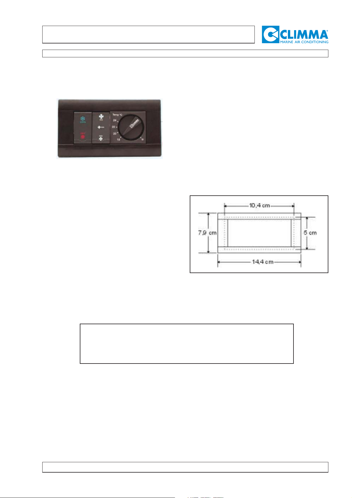
2.11- REMOTE PANEL
The control panel has the following functions:
A.- Start and stop
CONDIZIONAMENTO ESTIVO : premendo il tasto
SUMMER COOLING: Pushing the "COOL" button with ice
star mark.
WINTER HEATING: Pushing the "HEAT" button with
orange sun mark.
To stop the unit you must push the buttons "COOL" and
"HEAT" together.
B.- Setting of room temperature by thermostat
(TEMP).The thermostat has a 3 m long capillary with a
bulb, which must feel the return air (it must not touch the
evaporator fins).
C.- Adjusting the fan speed ( 3 speeds available )
Important: the low speed is selected pushing the two but-
tons "Max" and "Med" together.
2.11.A - LOCATION
When positioning the panel, one must consider that the
panel should be connected to the electrical box with the 3
m long cable and the thermostat bulb should be fastened
to the unit. If necessary, the bulb can be installed not
directly on the exchanger, but in the room. Anyway, it must
sense the ambient temperature. The bulb can be fixed
using the plastic plate supplied with it.
2.11.B.- INTERCHEANGEBLE BEZEL
The bezel supplied with the panel is black.
2.11.C - INSTALLATION
The panel is for flush installation and needs a cut out as
shown here on the right:
WARNING: The panel is connected to mains supply. It is absolutely necessary that,
when installed the back side of the panel, shall not be normally accessible. A plastic
cover is available on request in order to protect the back of the panel if accessible,
therefore dangerous.
Este manual sirve para los siguientes modelos
11
Tabla de contenidos
Otros manuales de Acondicionador de aire de Veco


