VC 11564 Documento técnico

MO_14511-K
Installations- und Betriebsanleitung
GERMANY
R
C
Änderungen in Technik, Design undAusstattung vorbehalten
VC-videocomponents.... aligned for professional videosystems
Dear Customer!
By selecting this VC product you have chosen a professional
device, which guarantees highest possible quality and
reliability.
Please read the following instructions carefully before
comissioning the product in order to be able to take full
advantage of all quality features regarding this product line.
GERMANY
R
CMounting and Operating Manual
Digital Video Recorder
©All contents of this document may change without prior notice
MO_11564/16.09.2011
Art. no. 11564

1

2
Copyright Notice
Information in this document is subject to change without notice. Our company may make
improvements or changes in this manual and CMS Software if necessary. The software, which
includes the information contained described in this document is furnished under a license agreement
and may be used or copied only in accordance with the terms of the agreement. It is against the law of
copyright to duplicate the software except as specifically allowed in the license agreement. No part of
this manual may be reproduced or transmitted in any form or by any means, including photocopy or
duplicate, for any purpose without prior written permission by our company.
This device complies with Part 15 FCC Rules. Operation is subject to the following two conditions:
(1) This device may not cause harmful interference.
(2) This device must accept any interference received including interference that may cause undesired
operation.
Safety Instructions
Warnings & Cautions
Please read the following safety warnings and keep this manual in a place which you can read
whenever you need.
1. Keep the Video Servers away from water, wet, hot, flammable area or with heavy moisture
2. Check the existing electric environment if it’s applicable (90V~240V AC) before use
3. Avoid to operate it in high temperature environment
4. Please put the Video Server and Hub in a flat stable place to operate
5. Do not disassemble the product arbitrarily.
This symbol indicates that personal injury may occur or the product may be
damaged when you fail to follow the given instruction
This symbol indicates that property loss may occur or the product may
malfunction when you fail to follow the given instruction
W
W
WA
A
AR
R
RN
N
NI
I
IN
N
N
C
C
CA
A
AU
U
UT
T
TI
I
IO
O
ON
N
N

3
Network IP Cameras
nCam Series: 2M/ High-Resolution CCD
Product Front View ProductRearView
Notes:
* For nCam Series cameras, the power is provided via POE by Gigabit POE HUB. Thus, it is not
necessary to connect the DC12V In (pin-3) and Gnd (pin-4) from the above illustration.
* Please use the CAT-6 LAN cable to connect each Telexper devices.
* The effective distance away from the nHub-4P POE Hub is 100 meters.
9. Gnd Gnd
8. Alarm In Alarm In
7. Audio Out Alarm Out
6. Audio Gnd Audio Gnd (for audio
in & out)
5. Audio In Audio In
4. GND GND
3. DC12V In DC12V In
2. D-(RS485) RS485 (D-)
1. D+(RS485): RS485 (D+)

4
Properties
2M/ High-Resolution CCD
CMOS / CCD Sensors, H.264 Compression
Resolution 640x480 @30fps
720x480 @30fps
PoE(Power over Ethernet) Hub to feed power
Built-in mechanical IR Cut Filter
Built-in Fixed/Manual/Auto Lens
IR LED 30~36PCSIR distance: 20M
4 Motion detection in one image
Linux OS
H.264/M-JPEG SOC dual compression
5
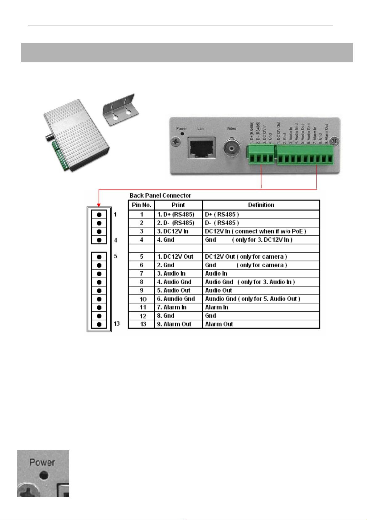
Video Server
Model: 11572
- Product Front View - Product Rear View
nVS-1P Back Panel Connector illustration
Notes:
* For nVS-1P, the power is provided via POE by Gigabit POE HUB. Thus, it is not necessary to
connect the DC12V In (pin-3) and Gnd (pin-4) from the above illustration.
* For nVS-1, nVS-1 doesn’t support the POE. Thus, please input the DC12V, 1.2A (min) electric
power in the DC12V In (pin-3) and Gnd (pin-4).
* Please use the CAT-6 LAN cable to connect each devices.
* Please use the 75 Ohm coaxial video cable connecting the camera and the video server.
* The DC12V Output at pin-5 provides the max 8W electric power.
* The nVS-1 Video Server requests the DC12V, 1.2A (min) electric power.
* The effective distance away from the nHub-4P POE Hub is 100 meters.
- The states of the Power LED
*
Red Color: Power on when connect with the nHub-4P (Gigabit POE HUB)
*
Red Flashiness: When the LAN is active

6
Properties:
1. Upgrade any Traditional Analogue Camera to the IP System
2. H.264 & M-JPEG Dual-type Codec
3. De-centralized & Modularized Design
4. Unlimited Number of Camera Expansion at any time
5. No Power Cable to Camera Required
6. Reduce minimum 50% of Installation Cost
7. Less Maintenance Cost than Analogue System
8. Up to 30fps @D1, 120fps@CIF Display & Recording
9. Multi Video Audio Streaming Design

7
Gigabit POE HUB
Model: 11574
- Product Front View
- Uplink : 10/100/1000Base-TX uplink ports for connect with the Wan / LAN
- POE 1-4: 10/100/1000Base-TX with POE injectors
- AC Input: for connected with power cable (Range 90V – 265V)
Model: 11575
- Product Front View
- The states of the LED
*Double Green lights: Giga-LAN
*Left Orange + Right Green light: Mega-LAN
Notes:
Power Provision Max DC48V, 300mA per each port

8
Network Video Decoder (Video Matrix)
Model: 11571
- Product Front View - Product Rear View
HDMIoutput
IR connector
VGAoutput
Embedded Linux Platform
Properties:
1. Provide H.264 video stream decode service.
2. VGA (D-SUB) and HDMI video output connector.
3. Real-time image decode 30fps, could display by full screen and quad screen.
4. High resolution D1 or CIFx4.
5. Support POE function.
6. CMS could provide monitoring, sequence display, alarm display, and etc functions.
7. Could work independently with only cameras, with or without CMS server.

9
RS485 Controller
Product Description
Each device provides the Video Server additional 4 set of the control unit, could use to connect 4
different alarm input and out-put devices.
Installation
Please connect the RS485 controller DT+ (D+) pin to the D+ pin of the Video Server, and also the
DT-(D-) pin to the D-pin of the Video Server. The power could provide from the 12V OUT pin of the
Video Server, and make sure both of the GND pin connected well to enable the power supply.
Model: 11573
- Product Front View -
Product Rear View
DIP Switch adjust table: BIT1~4 for ID, BIT5~7 for Baud Rate, BIT8 for transmission mode.
Properties:
1.Require the DC12V, 350mA input.
2.Provide the additional 4 set of alarm input and alarm output.
Tabla de contenidos
Otros manuales de DVR de VC


