P/N 146552999-1 (ML) • REV D • ISS 23MAY12 7 / 36
Detektorteknologien beskytter effektivt mod falske alarmer.
Undgå imidlertid mulige årsager til ustabilitet, f.eks.:
PIR-fare:
• Direkte sollys på detektoren
• Varmekilder inden for detektorens synsfelt
• Kraftig træk på detektoren
• Dyr i synsfeltet
• Blokering af detektorens synsfelt med store genstande
som f.eks. møbler
Mikrobølgefare:
• Monteringsoverflade modtagelig for rystelser
• Metaloverflader reflekterer mikrobølgeenergi
• Vandbevægelse gennem plastikrør
• Bevægelige eller vibrerende dele som blæsere, varme-
eller airconditionkanaler
Vi anbefaler, at alarmen gangtestes med jævne mellemrum, og
at kommunikationen med kontrolpanelet kontrolleres.
Sådan installeres detektoren:
1. Tag dækpladen af (se figur 2, pkt. 1 og 2).
2. Åbn forsigtigt detektoren med en skruetrækker (se figur 2,
pkt. 3 og 4).
Bemærk: Rør ikke den pyroelektriske føler (figur 6).
3. Tag dækskruen ud (figur 4, pkt. 2).
4. Gør soklen fast til væggen mellem 1,8 m og 3,0 m fra
gulvet.
Se figur 4.
- Ved flad montering bruges mindst to skruer (DIN 7998)
i position A.
- Ved hjørnemontering bruges skruer i position B eller C.
- For installation af vægsabotagekontakt ST400 bruges
monteringsposition A eller B. ST400-monteringsposition
vises som pkt. 3 i figur 4. Åbn kontakten i bagpladen
(figur 5, pkt. 2).
5. Tilslut detektoren (se figur 4 og 12). Brug bagpladens
ledningsindgange (figur 5, pkt. 1) og kabelrende (figur 5,
pkt. 3).
6. Vælg de ønskede indstillinger for jumper og DIP-switch
(se “Indstilling af detektoren” nedenfor for mere
information.
7. Fjern afdækningspladerne foran spejlet og indsæt
afdækningslabel, hvis dette kræves. Se “Indstilling af
dækningsmønster” på side 8 for flere detaljer.
8. Til loftmontering anvendes SB01-svingmonteringskonsol.
SB01-monteringspositionen vises som pkt. 1 i figur 4.
9. Luk detektoren, indsæt dækskrue og indsæt dækpladen.
Tilslutninger
Se figur 12.
Tabel 6: Detektortilslutninger
Terminal Etiket Forklaring
1, 2 GND,
+12V
Strømforsyningstilslutning (9 til 15 V, 12 V
nominel)
Terminal Etiket Forklaring
3, 4 ALARM Alarmrelæudgang (33 Ω). Brug jumper JA til at
sætte den indbyggede EOL-modstand i serie
med relæet. Se “Jumpere” nedenfor.
5, 6 TAMPER Sabotagekontaktudgang (0 Ω). Brug jumper JT
til at sætte den indbyggede EOL-modstand i
serie med kontakten. Se “Jumpere” nedenfor.
7 Gangtest Denne indgang aktiverer og deaktiverer LED
(gangtest til/fra). Gangtestfunktionen kan kun
vælges, når detektoren er i dagtilstand (pin 8).
Aktiv høj eller lav fastsættes af SW1-3 (se
“SW1-3: Polaritet” på side 8).
8 Dag/nat Det indstiller detektoren til dagtilstand (vis
hukommelse på LED-indikator) eller nattilstand
(aktiverer alarmhukommelsen og sletter
tidligere gemte alarmer). Aktiv høj eller lav
polaritet fastsættes af SW1-3 (se “SW1-3:
Polaritet” på side 8).
Noter
• Indgang 7 og 8 kan kun anvendes, når SW1-5 indstilles til
Ekstern til. Se “SW1-5: Ekstern funktion” på side 8.
•LED aktiveres kun, når SW1-6 indstilles til LED til.
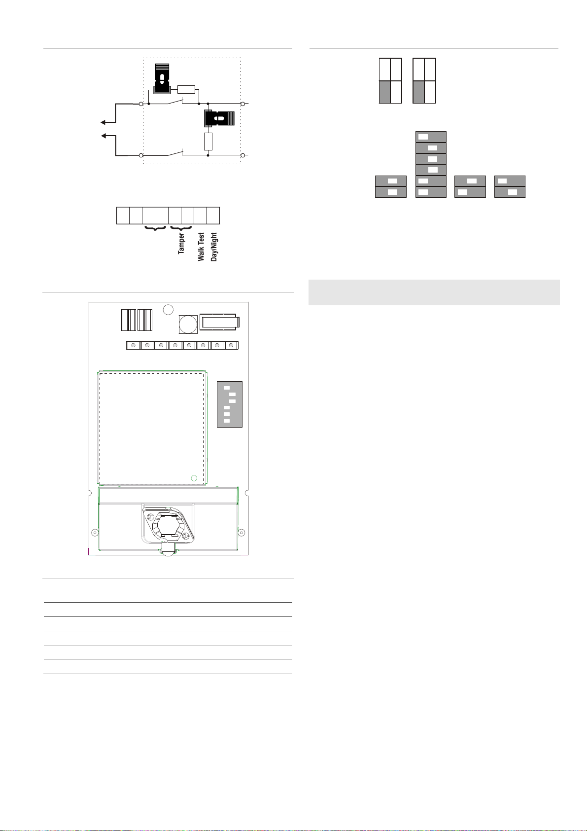
Figur 10 forklarer, hvordan man opretter en enkelt zone med
individuel indstilling af modstandene.
Figure 10 symbolforklaring
(1) Alarmrelæ
(2) Alarmzone
(3) Sabotagekontaktudgang
Ra Alarm EOL-modstand
Rt Sabotage EOL-modstand
Indstilling af detektoren
Se figur 13 om placering af jumpere og DIP-kontakt.
Jumpere
Jumpere, indstilling af indbygget EOL, tilstand og værdi.
Kredsløbet vises i figur 10.
JA: Indstil indbygget alarm EOL-modstand (Ra)
1 kΩ
2,2 kΩ
4,7 kΩ
(fabriksindstilling)
5,6 kΩ
OFF: Ingen indbygget alarm EOL.
JT: Indstil indbygget sabotage EOL-modstand (Rt)
1 kΩ
2,2 kΩ
4,7 kΩ
(fabriksindstilling)
5,6 kΩ
OFF: Ingen indbygget sabotage EOL.