Unitrol RST300-115-RIVET Manual de usuario

SOFT TOUCH FOR PNEUMATIC RIVETERS
RST300-115-RIVET (115VAC)
RST300-230-RIVET (230VAC)
Distributed by:

2 | SOFT TOUCH FOR PNEUMATIC RIVETERS
MODEL:
RST300-115-RIVET (115VAC)
RST300-230-RIVET (230VAC)
OPTIONS:
RST-403
RST-404
SERIAL NUMBER:
Thank you for purchasing this Unitrol SOFT TOUCH Safety System for your pneumatic
riveting machine. It is designed to protect your operator from serious pinch-point injury.
Please let us know if there are any questions or problems with the installation or use of
this product. You can contact us:
BY PHONE:
Monday - Friday 8:00 - 5:00 CT: 1-800-922-7533
BY EMAIL:
BY REGULAR MAIL:
Rockford Systems, LLC
5795 Logistics Parkway
Rockford, IL 61109
USA

SOFT TOUCH FOR PNEUMATIC RIVETERS | 3
WARRANTY
Unitrol Electronics provides a 5-year limited warranty to cover all of this SOFT TOUCH system. The
warranty periods are determined using the date the new control was originally shipped from Unitrol
Electronics. All warranty coverage is FOB Northbrook. Illinois.
This warranty, except for exclusions shown herein covers the following items:
DURING YEAR #1: All parts (exclusive of fuses) that fail due to manufacturing defects. Necessary
labor to repair control that has failed due to manufacturing defects.
DURING YEAR #2: 80% cost of all parts (exclusive of fuses).
80% cost of necessary labor to repair control that has failed due to manufacturing defects.
DURING YEAR #3: 60% cost of all parts (exclusive of fuses).
60% cost of necessary labor to repair control that has failed due to manufacturing defects.
DURING YEAR #4: 40% cost of all parts (exclusive of fuses).
40% cost of necessary labor to repair control that has failed due to manufacturing defects.
DURING YEAR #5:
20% cost of all parts (exclusive of fuses).
20% cost of necessary labor to repair control that has failed due to manufacturing defects.
EXCLUSIONS TO WARRANTY
Any expense involved with repair of control by other than Unitrol Electronics personnel that has not
been authorized in advance and in writing by an officer of Unitrol Electronics.
All costs for freight, to and from Unitrol Electronics, are excluded from this warranty
All field service labor, travel expense, and field living expenses associated with field service are
excluded from this warranty.
No coverage, parts or labor, is offered for components that have failed on control not being used as
specified in Unitrol Electronics published literature, technical sheets, and this direction book.
No warranty coverage will be made on controls that are being used contrary to specifications, that
were mechanically or electronically altered by customer or installer, or that were physically damaged
after shipment from Unitrol Electronics.
Damages to a control by lightning, flood, or mechanical damage are excluded from this warranty.
Unitrol Electronics assumes no liability for damage to other equipment or injury to personnel due to
a failure in the Unitrol Electronics control.
Unitrol Electronics shall not be responsible for any consequential damages of whatever kind.
Expenses involving alteration or installation of a Unitrol Electronics control are not covered in this warranty.
NO OTHER UNITROL ELECTRONICS INC. WARRANTY, WRITTEN OR IMPLIED, COVERS THIS CONTROL
UNLESS IN WRITING AND SIGNED BY AN OFFICER OF UNITROL ELECTRONICS, INC. PRIOR TO
SHIPMENT OF PRODUCT.

4 | SOFT TOUCH FOR PNEUMATIC RIVETERS
TABLE OF CONTENTS:
VERIFY YOUR SOFT TOUCH SENSOR BOARD IS CORRECT.......................................... 5
HOW SYSTEM OPERATES........................................................................................... 6
HOSE CONNECTIONS ................................................................................................. 7
PREPARING RIVETER...............................................................................................8-9
WIRING CONTROL: CONNECTING SIGNAL PICKUP WIRES......................................... 10
SCHEMATIC DRAWING.............................................................................................. 11
DEPTH SWITCH OPTION, RST-403, RST-404 .......................................................12-13
ADJUSTING SOFT TOUCH VALVES ............................................................................ 14
SETTING MAXIMUM DETECT TIME SWITCHES, BLANK TIME.................................... 15
STARTUP PROCEDURE ............................................................................................. 16
TESTING RIVETING MANDREL CLOSING FORCE ....................................................... 17
TROUBLE SHOOTING CHART .................................................................................... 18
LED INDICATOR LIGHTS............................................................................................ 19

SOFT TOUCH FOR PNEUMATIC RIVETERS | 5
VERIFY YOUR SOFT TOUCH SENSOR BOARD IS CORRECT
The SOFT TOUCH sensor board can be configured in several ways. Before turning power
on, check to be sure that the three switches are in the MFDC (up) position.
MFDC POSITION

6 | SOFT TOUCH FOR PNEUMATIC RIVETERS
SOFT TOUCH PINCH-POINT SAFETY SYSTEM
FOR INSTALLATION ON PNEUMATIC RIVETING MACHINES
HOW THE SYSTEM OPERATES:
When the voltage from the foot switch goes HIGH, this voltage goes to the 9280-TS7
SOFT TOUCH detection board, terminal #9.
The output terminal #11 (SVL) goes HIGH to turn on solenoid valve SVL.
This closes the riveting mandrel under low force using low air pressure on the forward
port of the riveter air cylinder.
The 9280-TS7 board checks input at terminals #4 and #5 to see if the voltage signal
drops a minimum value indicating that the riveting mandrel have made contact on a
conducting material (continuity detected).
If this contact is NOT sensed within the maximum time setting on the board’s DIPswitches*,
the output terminal #11 (SVL) will go LOW and drop out solenoid valve SVL to open the
riveting mandrel.
If this contact IS sensed within the maximum time setting:
• Terminal #11 (SVL) will continue to be HIGH
• Terminal #13 (SVH) will go HIGH
• Solenoid valve SVH will be turned ON to start high riveting mandrel pressure
*The maximum time the system uses for
detecting continuity is the TOTAL of the four
switches set on the DIPswitch block on the upper
left corner of the sensor board. Set it for about
1.5X the maximum time it takes to close the
mandrel on the part.
BLANK TIME: 50% of the DETECT TIME selected
will be used by the sensor board to block reaction
to continuity during this time. For example, if
the 1 and 0.5 DIPswitch paddles are closed
(1.5 second selection), continuity in the first 3/4
seconds will not turn on the full force.

SOFT TOUCH FOR PNEUMATIC RIVETERS | 7
HOSE CONNECTIONS
Note: If the riveting machine has an existing solenoid valve or pneumatic foot
switch, this system REPLACES these components.
Connect to point between air filter/
water trap and input to existing
pressure regulator.
Connect to air cylinder port that
opens the riveting mandrel. If cylinder
is spring return, install a 1/2” plug
into this bulkhead.
Connect to point after existing
airline lubricator.
Install two exhaust filters, provided with this system, into the two bottom ports.
Connect to air cylinder port that closes
the riveting mandrel.

8 | SOFT TOUCH FOR PNEUMATIC RIVETERS
PREPARING RIVETER
Tool Bar Type Mounting
The tooling bar must be electronically isolated from the riveter frame.
Counterbore the two screw pockets in the tooling bar so that they will clear the new
phenolic tubing, phenolic washers, and steel washers.
Drill and tap a hole in the tooling bar for connection to one of the blue wires from the
SOFT TOUCH system.

SOFT TOUCH FOR PNEUMATIC RIVETERS | 9
PREPARING RIVETER
Direct Tool Mounting Type
The lower tooling must be electronically isolated from the riveter frame.
Bore out hole in bottom of riveter and install phenolic or nylon sleeve and washers.
Drill and tap a hole in the frame and install a crimp terminal with one wire as shown.
Install a copper or brass terminal pad as shown and connect the other blue wire.
10 | SOFT TOUCH FOR PNEUMATIC RIVETERS
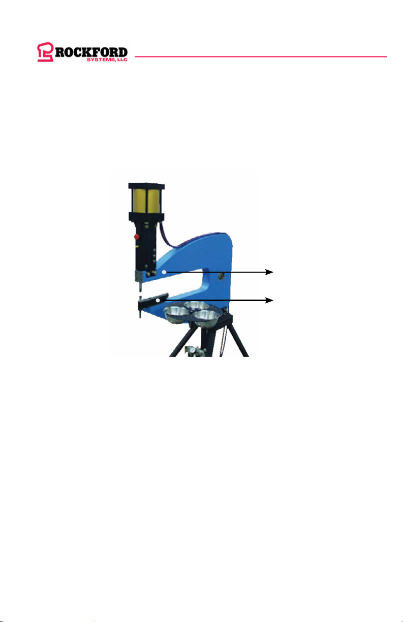
CONNECTING SIGNAL PICKUP WIRES:
1. Connect one of the blue wires from the SOFT TOUCH cabinet to a point on the
riveter frame.
2. Connect the second blue wire to the lower tool holding bar.
Connect two blue wires from the soft touch
enclosure to these two points
4
5
X
X
Este manual sirve para los siguientes modelos
1
Tabla de contenidos


