unication Uni Voice Manual de usuario


INDEX
Part 1. Preface............................................................................. 6
Preface ............................................................................................7
Part 2. System Introduction .................................................. 9
System Introduction .......................................................................10
Part 3. Installation........................................................ 11
Hardware Specication..................................................................12
Buttons ..........................................................................................12
LED Indicators ...............................................................................13
I / O ................................................................................................14
Installation .....................................................................................15
Part 4. Features............................................................ 19
Sending a Text Message ...............................................................20
Voice Paging .................................................................................31
Responder Status ..........................................................................39
Edit Personal Information ..............................................................43
Change Password .........................................................................45
Dispatcher Login Record ...............................................................47
Dispatcher Login / Logout..............................................................50
History Voice Message ..................................................................53
Event Category ..............................................................................56
Specialty Category ........................................................................59
Equipment Category ......................................................................63
Pager Data ....................................................................................67
Responder Data ............................................................................70
Group Data ....................................................................................74
Create / Edit System User .............................................................80
Change Password .........................................................................83
Edit Personal Information ..............................................................85
OTAP Management .......................................................................87
Send OTAP ...................................................................................90
OTAP History ...............................................................................100
OTA Password Setting ................................................................104
Sim Card Setting .........................................................................106
Login Log .....................................................................................108
Encryption Key ............................................................................110
Canned ACK Message ................................................................113
Establish Canned Message .........................................................116
System Time Setting ...................................................................120
WAN Setting ................................................................................123
LAN Setting (Local Area Network Setting) .......................................127
DDNS Setting ..............................................................................129
Transmitter Setting ......................................................................132
Time Sync....................................................................................135
Pager Programming Software .....................................................138
G1 Receiver Setting ....................................................................142
WAN Log .....................................................................................146
LAN Log.......................................................................................149
GSM Log .....................................................................................152
GPRS ACK Service Log ..............................................................156
DDNS Log ...................................................................................159
Web Server Log...........................................................................162
Transmitter Log ...........................................................................166
Authority Log ...............................................................................169
Power On / Off Log ......................................................................172
G1 Receiver Log..........................................................................176
System Service Log.....................................................................180
Emergency Call Record...............................................................183
Dispatching Attendance...............................................................186
Responder Attendance ................................................................190
Incident Rate ...............................................................................193
Part 5. Others ............................................................. 197
Basic Troubleshooting .................................................................198

Uni Voice
Pager Console
■ Preface
1. Voice / Message Pager Console is an epochal dispatch
system, which innovated the limitations of paging system
that has been existed for 40 years. The products like pager
do have the irreplaceable importance in the technology
developed age. The variable message broadcasting func-
tions such as personal calls, group calls and all calls make
the message sending rapidly in a short time. Easy to install,
wide communication coverage, and strong signal pen-
etrability, stable system, no environmental constraints on
message sending, not easy to be damaged while there’s a
natural disaster, small size, low power consumption, easy
to carry. All these features make the pager the best system
when you need to gather mass human resource rapidly in
the eld of social security and homeland security.
2.The pager we were using is an one way paging system
which means the sender usually do not know if the message
has been received or not, nor do we know the reaction of
receiver. Now, the Unication introduces a dual communica-
tion system (GSM/GPRS) without alter the feature of pager
broadcasting. The dual communication system uses system
message to auto reply, makes the sender to know if mes-
sages has been received or read, and to reply message.
This feature makes up the defect of paging system since it
was established.
3. To realize this epochal idea, there must be an integrated
idea between sender and receiver, therefore, besides E5 /
G1, Unication also offer a pager console for system integra-
tion.
4.The current console systems on the market, either private-
purchased for on-site using for alpha or voice pager, or the
consoles offered by paging carrier for the user to connect
region or wild area, basically are only a tool or a platform
Part 1. Preface
7

Preface Uni Voice
Pager Console
for messages transmission but not able to support the nec-
essary dispatching and managing requirement to a console.
Unication has made a great innovation to a console. We
implement the Internet technology and cellular phone 3G
transmission technology to Unication Pager Console and
bring “Motion Dispatching” into the traditional paging mar-
ket.
This concept provides the users including the “System Ad-
ministrator” and ” Dispatcher” to send messages, or dis-
patch through the Internet/Intranet by PC, NB or Unication
3G cellular phone MT3.
Note:The “System Administrator” and ” Dispatcher” can be one
person or even a group of people.
Note:Unication Pager Console can be used on the GSM/GPRS sys-
tem and 2-way radio system, but only Unication MT2 / U3
can support this application.
5.Traditional consoles usually only support one protocol trans-
mission (For example, POCSAG or Flex), but Unication Pag-
er Console allows the users to send messages though two
protocol system (POCSAG and Flex) at the same time.
6. Also Unication Pager Console can connect with multi-pag-
ing carrier system to support the message transmission be-
tween the different paging carriers. This capability lessens
the limitation on recruiting the volunteer rescuers. For some
volunteers, who are already attending one rescue organiza-
tion may be willing to join other organizations regardless
of the protocol of communication device. (For example,
people who may already wear Flex pagers for a rescue or-
ganization, the willing of them to join another organization
which may provide POCSAG pager will be less, since they
need to wear two different pagers.)
Part 2. System Introduction
8 9

System
Introduction Uni Voice
Pager Console
■ System Introduction
Part 3. Installation
10 11

Hardware
Specification Uni Voice
Pager Console
1
2 3 4
Front View
Buttons
Item Button Function
1 Power Powers on/off the Uni Voice Pager Console.
2 Menu Depress to display the WAN and LAN
addresses.
3Navigation
Key
Up-WAN Reset or LAN Reset
Down- WAN Reset or LAN Reset
OK- Conrm the function
4 Cancel Cancels the current operating function.
■ Hardware Specification
1 2 3 4
13
10
11 12
56789
LED Indicators
Item LED&LCD Function
1 Power LED The Power LED ashes green under normal operation. It will ash
when the system detects an abnormal condition.
2 WAN LED The WAN LED ashes green when WAN status is normal or red if an
abnormal condition is detected.
3 LAN LED The LAN LED ashes green when the status is normal or red if
anabnormal condition is detected.
4Database
LED
The Database LED ashes green when the status is normal or red
when an abnormal condition is detected.
5WEB
Server LED
The WEB Server LED will ash green when the status is normal or red
if an abnormal condition is detected.
6 GSM 1 LED The GSM1 Status LED will ash green when GSM status is normal or
red if an abnormal condition is detected.
7 GSM 2 LED The GSM2 Status LED will ash green when GSM2 status is normal or
red if an abnormal condition is detected.
8 TX 1 LED The Queue Server 1 Status LED will ash green when the server is
operating normally or if an abnormal condition is detected.
9 TX 2 LED The Queue Server 2 Status LED will ash green when the server is
operating normally or red when an abnormal condition is detected.
10 G1 Receiver
LED
The G1 Receiver LED will ash green when the status is normal or red
if an abnormal situation is detected.
11 Front Panel
Indicator
The front panel indicator displays the information of the Uni Voice
Pager Console.
12 GSM
Strength LED
The GSM Strength LED has 5 bars, each bar indicates different signal
strength, the LED lights green when signal strength is normal and the
lights will turn off when no GSM signal has been detected.
13 HD 1 &
HD 2 LED
The LED on Hard Disk ashes green when the hard disk is operating
normally or red if an abnormal condition is detected.
12 13
Hardware
Specification Uni Voice
Pager Console
1
2
3
4 5 6
7
8
9
10
11
12
13
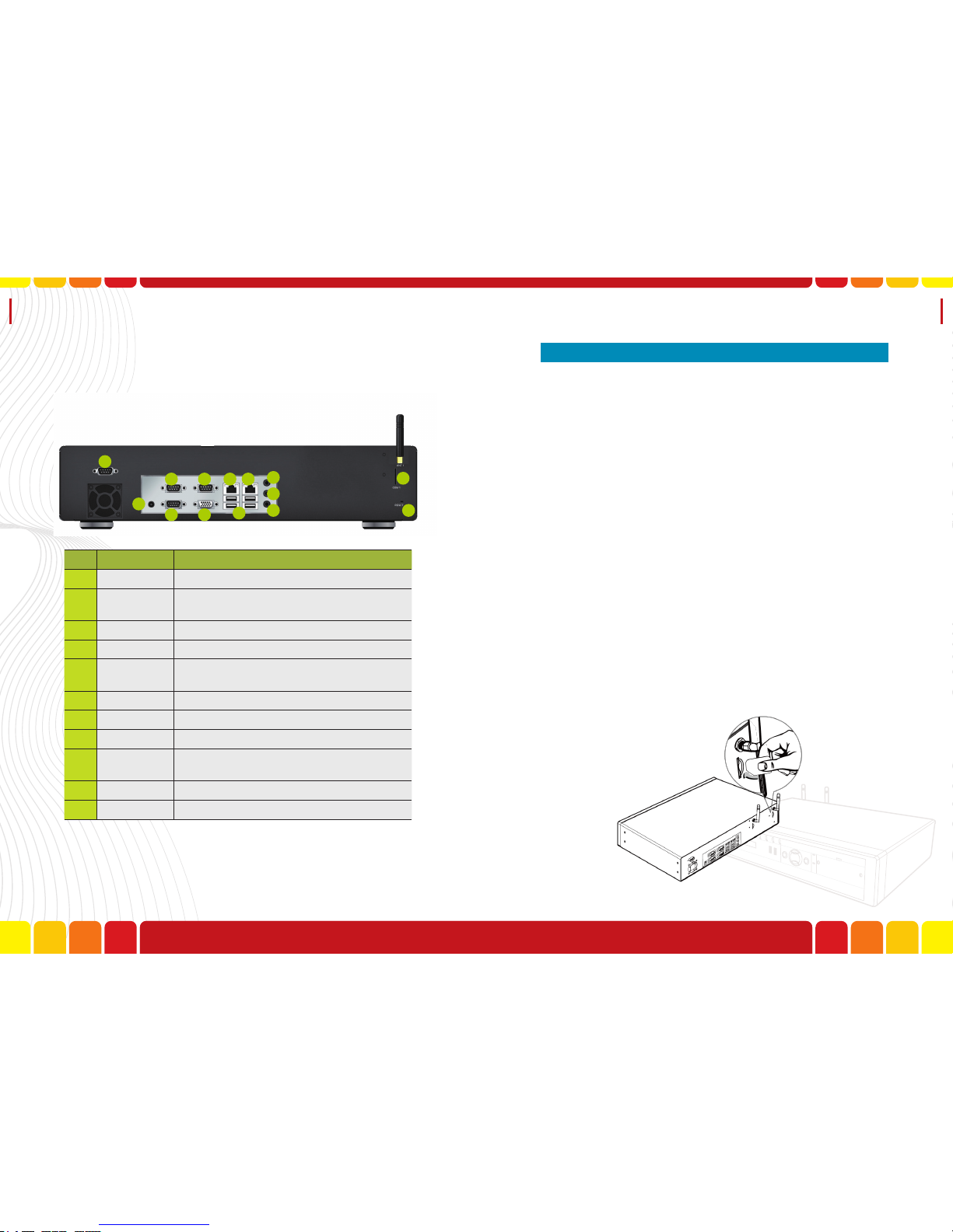
14
Item I/O Function
1 DC-In Power Input.
2-4 COM 1-3 Future.
5 LAN Local Area Network connection.
6 WAN Wide Area Network connection.
7 USB Port 1-4 Data I/O.
8 LIN Voice Input.
9 SPK Voice Output.
10 MIC Microphone Input.
11 GSM Slot &
Antenna GSM SIM Card and Antenna.
12 Reserved No Use.
13 VGA Future.
Rear View
I / O There are 6 steps to complete the hardware installation.
1. GSM SIM Card Installation
2. LAN Installation
3. WAN Installation
4. Power Installation
5. G1 Receiver Installation-Connect G1 Receiver with
RS-232 cable.
6. Audio Cable Installation-Connect G1 Receiver and
Voice Pager Console with Audio Cable for voice
data transmission.
7. GSM Antenna Installation
8. Power on Messaging console
1.GSM SIM Card Installation
Step1. Insert SIM card.
■ Installation
14 15

Installation Uni Voice
Pager Console
2.LAN installation
Step1.Connect the RJ45 cable to the LAN port curd
the hub switch
3.WAN installation
Step1.Connect the RJ45 cable to the WAN port curd
the hub switch
4.Power Adaptor Installation
Step1.Determine your power cord type. Put the pow-
er connector to the DC-IN port, and the other
to the power socket.
Step2.Plug in the power cord to your Messaging Con-
sole and the power source.
16 17

Installation
5.GSM Antenna Installation
Step1.Plug the GSM antenna to the antenna port(port
No.11 and 12), If you have select the Antenna
Extension, please assemble one side of anten-
na extension connector to Console, then con-
nect the other connector to your GSM antenna.
6.Power on Messaging Console
Step1. Press the Power key to turn on.
Part 4. Features
18
Otros manuales para Uni Voice
1
Tabla de contenidos


