NST13308-P914_A 2020-06-10 Page 4
1) Receiver Output Voltages
A) The receiver has four output voltage (channels) which will operate four separate circuits. The
output voltage is 12 volts direct current (vdc).The maximum drive current for each of the four
output channels is 5 Amps (maximum) . The four outputs can turn On (drive) bulbs, relay coils or
small motors.
B) Check the power requirement for the bulb or motor before connecting to the receiver.
Maximum 5 amps @ 12vdc or 60 watts @ 12vdc
2) Determine where the receiver and antenna will be located.
Typically the RF receiver is located under the dash or behind a wall panel in the back. If the receiver
is to be mounted outside the cab area then you must protect the receiver. The receiver is NOT
waterproof or moisture resistant*.
DO NOT mount the receiver and antenna:
A) Within 6 feet of a motor
B) Near lar ge bundles of wires
C) Near other antennas or RF devices
D) The antenna should not be touching any metal as this grounds the RF (radio
frequency) signal
*T ouchTronics offers weather resistant housings for many different types of applications. Call the
factory @ 1-800-294-2570 for information on yourparticular application needs.
Installation: Planning
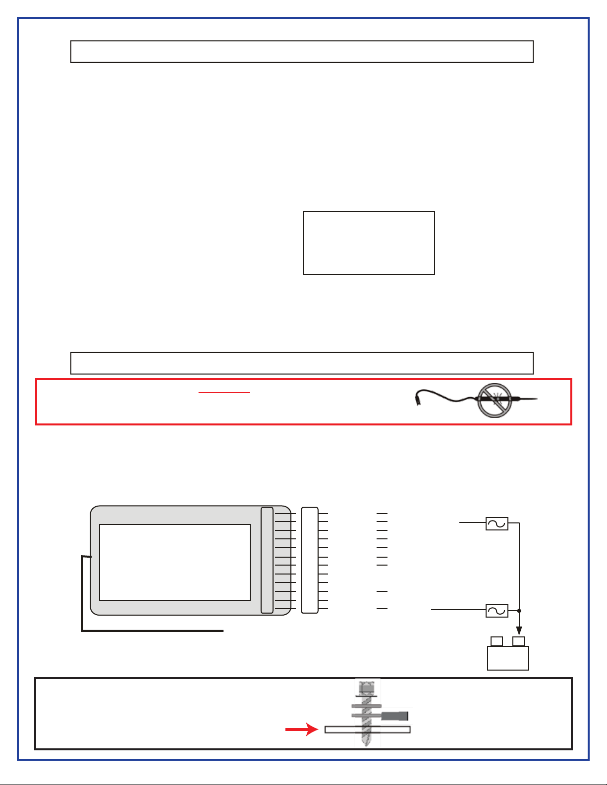
Installation: Receiver
(-)
Battery
(+)
12
11
10
09
08
07
06
05
04
03
02
01
PowerT ouch Remote Contr ol System
Series 914 RF Receiver
This device complies with FCC rules part 15.
Operation is subject to the following 2 conditions:
1) This device may not cause harmful interference
2) This device must accept any interference received
including that causing undesired operation
9” Antenna Wire
*Maximum output current 5 Amps. Overcurr ent will damage outputs.
1a Maximum
12
11
10
09
08
07
06
05
04
03
02
01
White/Tan
Purple
Tan
Green/Black
Yellow/Black
Green/Red
Yellow/Red
Empty
Orange
Black
Empty
Red
Ch 4 - Output, 5 amp
Power +12v - 5 amp
Ch 3 - Output, 5 amp
Ch 1 - Input for rr@g circuit (-)*
Ch 2 - Input for rr@g circuit (-)*
Ch 1 - Output, +12v, 5 amp
Ch 2 - Output, +12v, 5 amp
Empty
Do Not Use
Chassis Ground
Empty
Logic +12v
*RR@G - Reversal Rest @ Gr ound
Notes:
1) Channels 1 and 2 are momentary outputs as long as the button is pressed.
2) Channels 3 and 4 are factory set as momentary outputs as long as the button is pressed. These outputs can be
programmed as latching (push on - push off). Call the factory for program information at 1-800-294-2570
10a Maximum
Range of your Remote
Control is affected by
the installation location
of the receiver antenna
Warning!
Use only a voltmeter to check voltage during installation and testing.
*Using a test light WILL damage the outputs!
*See Note Below
Scrape paint and clean area before installing ground screw
#10 x 3/4” Screw
#10 3/16” Star Washer
#10 3/16” Ring Terminal
Vehicle Frame
CHASSIS GROUND