Torin BIG RED T820014S Manual de usuario

OWNER’S MANUAL
2 TON TROLLEY JACK
Item: T820014S
Version 06232020
REGISTER
YOUR PRODUCT
http://www.torin-usa.com/
customer-support/
register-a-product.html
SCAN CODE
Questions, problems, missing parts? Before returning to your retailer, contact our customer service
department at www.torin-usa.com/support.
Read carefully and understand all ASSEMBLY AND OPERATION INSTRUCTIONS before operating.
Failure to follow the safety rules and other basic safety precautions may result in serious personal
injury.

2
TECHNICAL SPECIFICATIONS
Item Capacity Lifting Range
Min. (Inch)
Lifting Range
Max. (Inch)
Lifting Range
Min. (cm)
Lifting Range
Max. (cm)
T820014S 2 TON 5-5/16 13 13.5 33
SAFETY MARKINGS
1. Study, understand, and follow all instructions before operating this device.
2. Do not exceed rated capacity.
3. Use only on hard, level surfaces, with less than 3 degrees of slope.
4. Lifting device only. Immediately after lifting, support the vehicle with appropriate means.
5. Do not move or dolly the vehicle while on the jack.
6. Lift only on areas of the vehicle as specied by the vehicle manufacturer.
7. No alterations shall be made to this product.
8. Only attachments and/or adapters supplied by the manufacturer shall be used.
9. Do not get under or allow anyone under the vehicle until it has been supported by jack stands.
10. Center load on saddle prior to lifting.
11. Use wheel chocks or other blocking device on opposing wheels before using jack.
12. Never use on a lawn mower or lawn tractor.
13. Do not use this jack for any use other than the manufacturer specied usage.
14. Do not rock the vehicle while working on or around equipment.
15. The following are not recommended for supporting on this equipment: Foundations, Homes, Mobile
Homes, Trailers, RV’s, Campers, nor Fifth Wheels, etc...
16. Failure to heed these markings may result in personal injury and/or property damage.
WARNING!

3
ASSEMBLY
1. Familiarize yourself with the jack.
2. Line up the bottom of handle to the release valve
located under the handle socket. Turn handle and
release valve Clockwise to Tighten.
3. Secure the handle in place inside the handle
socket. Without any vehicle on the jack, cycle
the lift up and down several times to insure the
hydraulic system is operating properly. (Perform
the System Air Purge Procedure before rst use.)
Lifting Arm
Saddle
Front Wheel
Handle
Pump Plunger
Oil Fill Plug
Rear Swivel
Casters
Cover Plate
SYSTEM AIR PURGE PROCEDURE
IMPORTANT: BEFORE FIRST USE
Perform the following System Air Purge Procedure to
remove any air that may have been introduced into
the hydraulic system as a result of product shipment
and handling. This step is to be completed without
any weight on the jack.
1. Turn release valve counterclockwise one full turn
to the open position.
2. Rapidly pump the handle 6-8 times. Leave handle
in down position to expose oil ll plug.
3. Remove cover plate.
Cover Plate
4. With a at blade screwdriver, push the oil ll plug
slightly to the side to purge trapped air from
system. (Use caution not to tear or puncture the
oil plug.)
Screwdriver
6. Turn release valve clockwise to the closed
position.
5. Replace cover plate and the jack is now ready for
use. Check for proper pump action.

4
BEFORE USE
OPERATION
1. Before using this product, read the owner's manual completely and familiarize yourself thoroughly with the
product and the hazards associated with its improper use.
2. Perform the air purge procedure. (See System Air Purge Procedure.)
3. Check and that the pump operates smoothly before putting into service.
4. Inspect before each use. Do not use if bent, broken or cracked components are noted.
1. Block the vehicle’s wheels for lifting stability. Secure the load to prevent inadvertent shifting and movement
2. Position the jack near desired lift point.
3. Set the Parking Brake in the vehicle.
4. Refer to the vehicle manufacturer owner’s manual to locate approved lifting points on the vehicle. Position
the jack so that the saddle is centered and will contact the load lifting point rmly.
5. Assemble the handle; ensure to align with slots.
6. Close the release valve by turning it clockwise until it is rmly closed.
7. Before raising the vehicle double check and verify the saddle is centered and also has full contact with the
lifting point.
8. Pump handle to lift until saddle contacts load. Continue to pump the jack handle to lift the vehicle to the
desired height. After lifting, support the load with appropriately rated vehicle support stands before working
on the vehicle.
RAISING THE JACK
CAUTION: NEVER WIRE, CLAMP OR OTHERWISE DISABLE THE LIFT CONTROL VALVE TO
FUNCTION BY ANY MEANS OTHER THAN BY USING THE OPERATOR'S HAND. USE THE HANDLE
PROVIDED WITH THIS PRODUCT OR AN AUTHORIZED REPLACEMENT HANDLE TO ENSURE
PROPER RELEASE VALVE OPERATION. DO NOT USE EXTENSIONS ON THE OPERATING
HANDLE.
1. Raise load high enough to allow clearance for the jack stands to be removed, then carefully remove jack
stands.
LOWERING THE JACK
2. Remove support stands.
3. Grasp the handle rmly with both hands. Securely hold on to the jack handle so your hands do not slip and
ensure the release valve does not rapidly lower.
4. Carefully open the Release Valve by slowly turning the handle counter-clockwise. (Do not allow bystanders
around the jack or under the load when lowering the jack.
5. After removing jack from under the load, keep jack in the lowered position to reduce exposure to rust and
contamination.
WARNING: USE EXTREME CAUTION WHEN LOWERING THE JACK. THE JACK HANDLE MAY TURN
RAPIDLY. OPENING THE RELEASE VALVE TOO FAST CAN CAUSE THE JACK TO LOWER RAPIDLY.
FAILURE TO HEAD THESE WARNINGS COULD CAUSE SERIOUS INJURY OR DEATH.

5
If you use and maintain your equipment properly, it will give you many years of service. Follow the
maintenance instructions carefully to keep your equipment in good working condition. Never perform any
maintenance on the equipment while it is under a load.
Inspection
You should inspect the product for damage, wear, broken or missing parts (e.g.: pins) and that all components
function before each use. Follow lubrication and storage instructions for optimum product performance.
Binding
If the product binds while under a load, use equipment with equal or a larger load capacity to lower the load
safely to the ground. After unbinding; clean, lubricate and test that equipment is working properly. Rusty
components, dirt, or worn parts can be causes of binding. Clean and lubricate the equipment as indicated in
the lubrication section. Test the equipment by lifting without a load. If the binding continues contact Customer
Service.
Cleaning
If the moving parts of the equipment are obstructed, use cleaning solvent or another good degreaser to clean
the equipment. Remove any existing rust, with a penetrating lubricant.
Lubrication
This equipment will not operate safely without proper lubrication. Using the equipment without proper
lubrication will result in poor performance and damage to the equipment. Some parts in this equipment are not
self-lubricating. Inspect the equipment before use and lubricate when necessary. After cleaning, lubricate the
equipment using light penetrating oil, lubricating spray.
• Use a good lubricant on all moving parts.
• For light duty use lubrication once a month.
• For heavy and constant use lubrication recommended every week.
• NEVER USE SANDPAPER OR ABRASIVE MATERIAL ON THESE SURFACES!
Rust Prevention:
Check rams and pump plungers on the power unit assemblies daily for any signs of rust or corrosion.
Without a load, lift the equipment as high as it goes and look under and behind the lifting points. If signs of
rust are visible clean as needed.
Grease Fittings
Some models contain grease ttings that will regularly need to be greased and lubricated.
How the Jack Operates
With release valve closed, an upward stroke of the jack handle draws oil from the reservoir tank into the
plunger cavity. Hydraulic pressure holds the valve closed, which keeps the oil in the plunger cavity. A
downward stroke of the jack handle releases oil into the cylinder, which forces the ram out. This raises the
saddle. When the ram reaches maximum extension, oil is bypassed back into the reservoir to prevent an over
extended ram stroke and possible damage to the jack. Opening the release valve allows oil to ow back into
reservoir. This releases hydraulic pressure on the ram, which results in lowering the saddle.
Storing the Jack
1. Lower the Lifting ram.
2. Place the handle in the upright position.
3. Store in a dry location, recommended indoors.
Note: If the jack is stored outdoors, be sure to lubricate all parts before and after use to ensure the jack stays
in good working condition. Always store jack in the fully retracted postion when stored in outdoor or caustic
enviroments that can cause corrosion and/or rust.
MAINTENANCE INSTRUCTIONS
6
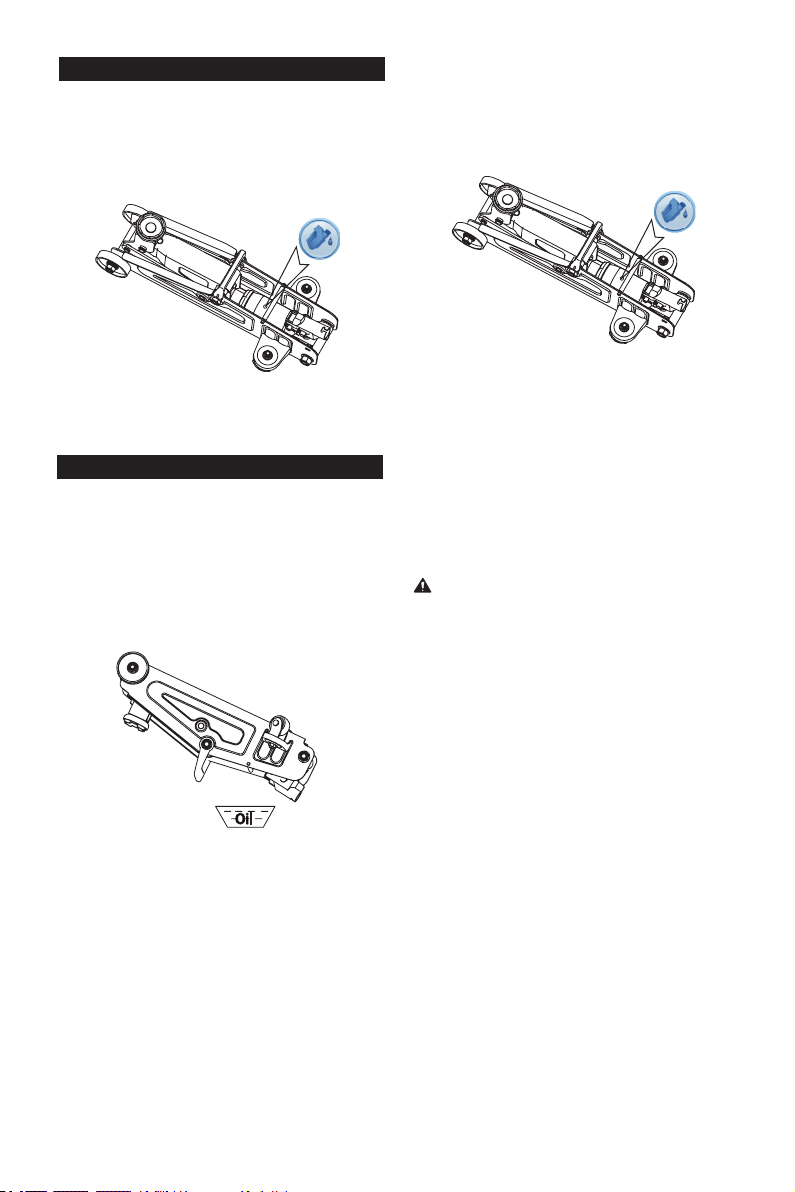
TO ADD JACK OIL
1. Position the jack on level ground and lower the
saddle.
2. Remove cover plate.
3. Remove the oil plug.
4. Fill the oil case until oil level is just beneath the
lower rim of the oil ll hole.
TO REPLACE JACK OIL
1. Position the jack on level ground and lower the
saddle.
2. Open release valve by turning handle counter-
clockwise.
3. Remove cover plate.
4. Remove the oil plug.
5. Turn the jack upside down to drain old oil from the
oil ll hole.
5. Replace oil plug.
6. Replace coverplate and perform the System Air
Purge Procedure.
6. Position the jack on level ground and keep saddle
in the lowered position. Fill the oil case until oil
level is just beneath the lower rim. Keep dirt and
other foreign materials clear when pouring.
7. Replace oil plug.
8. Replace the cover plate and perform the System
Air Purge Procedure.
• DO NOT USE MOTOR OIL IN THE JACK.
• ONLY USE ANTI-FOAMING JACK OIL.
• ALWAYS USE A GOOD GRADE HYDRAULIC
JACK OIL.
• DO NOT USE HYDRAULIC BRAKE FLUID,
ALCOHOL, GLYCERINE, DETERGENT, MOTOR
OIL OR DIRTY OIL.
• USE OF A NON-RECOMMENDED FLUID CAN
CAUSE DAMAGE TO A JACK.
• AVOID MIXING DIFFERENT TYPES OF FLUID
AND NEVER USE BRAKE FLUID, TURBINE
OIL, TRANSMISSION FLUID, MOTOR OIL OR
GLYCERIN. IMPROPER FLUID CAN CAUSE
PREMATURE FAILURE OF THE JACK AND THE
POTENTIAL FOR SUDDEN AND IMMEDIATE
LOSS OF LOAD.
• DISPOSE OF HYDRAULIC FLUID IN
ACCORDANCE WITH LOCAL REGULATIONS.
ADDITIONAL LUBRICATION:
1. Periodically check the pump piston and ram for
signs of rust or corrosion. As needed thoroughly
wipe with a clean non-scratching oil soluble
cloth. NEVER USE SANDPAPER OR ABRASIVE
MATERIAL ON THESE SURFACES!
2. When not in use, store the jack with pump piston
and ram fully retracted.
ADDITIONAL WARNINGS:

7
8
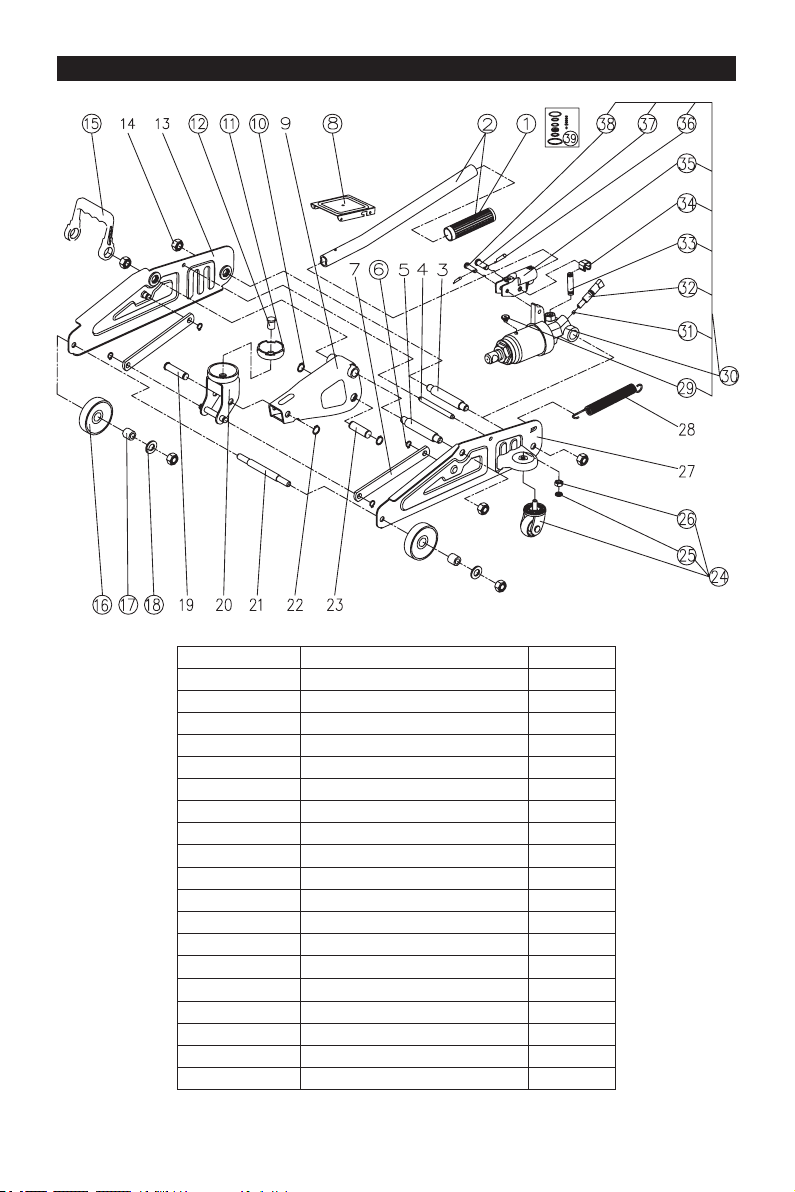
ASSEMBLY DIAGRAM
REF# DESCRIPTION QTY
21 Shaft for front wheel 1
22 Circlip 12 1
23 Pin 1
24 Rear caster 2
25 Retaining washer 8 2
26 Nut M8 2
27 Left wall plate assembly 1
28 Return spring 1
29 Oil plug 1
30 Power unit assembly 1
31 Steel Ball Bearing 1
32 Valve pistion 1
33 Pin base 1
34 Moust Piston 1
35 Handle socket 1
36 Retaining pin 2
37
Pin 1
38
Pin 1
39
Seal kit 1

9
TROUBLESHOOTING
JACK
WILL
NOT
LIFT
LOAD
JACK
WILL
NOT
HOLD
LOAD
JACK
WILL
NOT
LOWER
POOR
JACK
LIFTING
WILL NOT
LIFT TO
FULL
EXTENSION
CAUSES AND SOLUTIONS
Release valve is not completely closed
(Turn handle clockwise).
Weight Capacity Exceeded.
Air is in the hydraulics.
Purge air from system.
Low oil level. Add oil as required.
Oil reservoir is overlled.
Drain excessive oil.
Lubricate moving parts.
Jack is binding or foreign obstruction
Power unit malfunctioning.
Replace the power unit.
X XX
X
X X
X X XX
X X X
X
X
Safe Operating Temperature is between 40°F – 105°F (4°C - 41°C)
WARRANTY NOTICE
WARRANTY INFORMATION
We want to know If you have any concerns with our products. If so, please call toll-free for Immediate
assistance. For additional web customer support help inquiries visit the Customer Service section at: http://
www.torin-usa.com.
This service jack is covered under a 1-year limited warranty when used as recommended. Only those
items listed with a Part # are available for purchase. For assistance with the operation or the availability
of replacement parts, contact our Parts and Warranty Department at www.torin-usa.com/support. Please
have available a copy of your receipt, the model number of the product, serial number, and specic details
regarding your question.
Not all equipment components are available for replacement; illustrations provided are a convenient reference
of location and position in the assembly sequence.
The manufacturer reserves the rights to make design changes and or improvements to product lines
and manuals without notice.

MANUEL DU PROPRIÉTAIRE
CRIC ROULEUR 2 TONNES
Article No. TA82001
ENREGISTREZ
VOTRE PRODUIT
http://www.torin-usa.com/
customer-support/
register-a-product.html
SCANNEZ LE CODE
Questions, problèmes, pièces manquantes? Avant de retourner voir votre fournisseur, appelez notre
service à la clientèle au www.torin-usa.com/support.
Lisez attentivement et comprenez toutes les DIRECTIVES DE MONTAGE ET DE FONCTIONNEMENT
avant l’utilisation. Vous pouvez subir des blessures graves si vous ne vous conformez pas à ces
règles et autres précautions de sécurité.
AVERTISSEMENT!
Tabla de contenidos
Idiomas:
Otros manuales de Jacobo de Torin BIG RED

Torin BIG RED
Torin BIG RED TH932001B Manual de usuario

Torin BIG RED
Torin BIG RED TZ200012 Manual de usuario

Torin BIG RED
Torin BIG RED T82454 Manual de usuario

Torin BIG RED
Torin BIG RED TRQ50002 Manual de usuario

Torin BIG RED
Torin BIG RED T830023 Manual de usuario

Torin BIG RED
Torin BIG RED TRA8485 Manual de usuario

Torin BIG RED
Torin BIG RED TR4053 Manual de usuario

Torin BIG RED
Torin BIG RED TR4055 Manual de usuario

Torin BIG RED
Torin BIG RED T10152 Manual de usuario

Torin BIG RED
Torin BIG RED T830020 Manual de usuario