fewer. Please remove the left cabinet first to avoid excessive work or
damage of other parts.
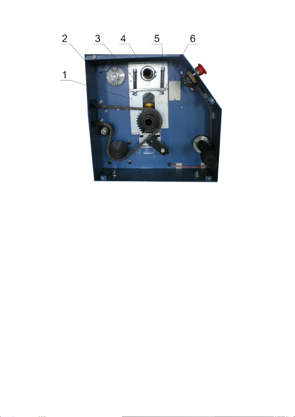
As the figure shown above, the middle bracket of the left compression and
the upper compression bracket are connected by two bolts. Each bolt has a
spring and two screws (see the figure above). One screw is welded with the
compression plate and the other below is movable clamp nut.
2) If the image is off-tracking on the left right of the machine, it indicates
the pressure on the left side is higher than that on the right side. Adjust the
screw bolt to reduce the deflection of the spring on it. The range of
adjustment of both bolts shall be as the same as possible.
Note: You can use a ruler to measure the height of the two bolts and make
sure they are at the same level in the adjustment.
3) If the image is off-tracking on the right side, it indicates that the
pressure on the level side is lower than that on the right side. Increase the
deflection of the spring on the two bolts then. The range of adjustment
depends on the range of off-track of image.
Caution: When the deflection of spring is adjusted, please turn the pressure
of the machine to its maximum level to ensure there is margin for the
deflection. Or else the spring may be damaged. When the left side does not
have margin, remove the right-side board to adjust the screw bolt on this
side.
4)Tighten the nuts after adjustment.
5) Install the left side board on the machine.
Adjustment principle: if the image is off-tracking to the left side, the
pressure of the left side is higher than the right side. Loosen the spring on
the left side to reduce its deflection.
1. Align the main rollers
Set the space between the main rollers to 1-2mm. Observe the evenness of space