ToolMaster TM-U3 Manual de usuario

INSTRUCTION MANUAL
TM-U3
Universal D BIT Grinder (240V)
1/4HP
G1975

GRINDING SPINDLE
The spindle bearing has been factory-adjusted to exclude play while allowing for free-running of
the spindle. In the event some play develops in the course of time, such play should be taken
up by tightening the two nuts M. for this purpose, pull spindle from its seat after having loosened
screw S and removed the parts as indicated When tightening the nuts allow for a freerunning
spindle. Excessive tightening will result in bearing failure. After reinserting the spindle assembly
carefully tighten screw S in the bore, to hold the spindle assembly in position:
Wheel Replacement
To remove Grinding wheel you need to lock the spindle.
Firstly remove cup head cap screw (spindle lock screw)
Then line up hole in the spindle with the bolt hole,
may need to move spindle forward or back to correctly align
Use a pin to lock the spindle and the special tool to undo the wheel nut
Fit new wheel, tighten nut, remove pin and replace screw

Nomenclature of Controls
The details below are used in most of the procedures listed in this manual, unless otherwise stat-
ed.
D Wheel dressing attachment
A Spring collet clamping quill
T1 Cross slide clamping lever
S2 Vertical swivel mount setting scale
T2 Vertical swivel mount clamping lever
T3 Horizontal swivel mount clamping lever
T4 Tubular guide clamping lever
F Horizontal swivel mount index drum
T7 Clamping lever for adjustment along tubular guide
H Indexheadbracketneadjustmentscrew
G Adjustable stop screw
T5 Index head slide clamping lever
C Cutter lip aligning gauge
C1
P
S
Cross slide vernier scale for off-center radii
Spring collet index pin
Index head slide
S5 Indexheadslideneadjustmentsetscrew
S1 Indexheadslideneadjustmentscrew
Q Cross slide
T6 Index durm F clamping lever
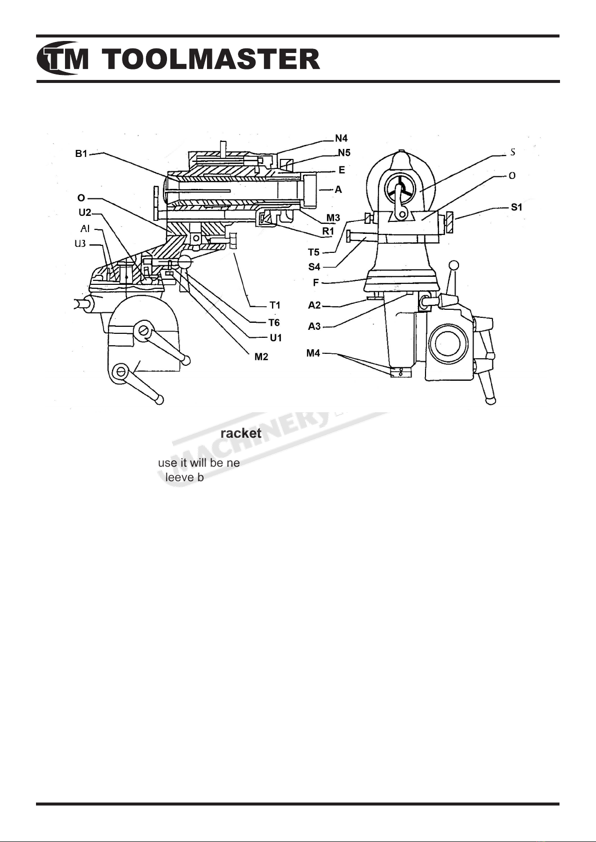
B1 Collet sleeve
U2 Screw
A1 Stop plate for 90 degree
U3 Screw for Al
N4 Index drum
N5 Ring nut
E Index ring bearing sleeve
M3 Nut for index sleeve
R7 Slotted disc
A3 Adjusting eccentric pin
M4 Nut
INDEX HEAD
Servicing The Index Head Bracket
General
After a major period of use it will be necessary to dismantel the index head bracket and to clean
and lubricate the collet sleeve bearing, the index head slide, and the swivel arm.
Collet Sleeve Bearing
To remove the collet sleeve proceed as follows: Remove ring nut N5, index drum N4, and index
ring, in that order. Remove two M3 nuts out of the index bearing sleeve E. There is a annular
grease chamber in the longitudinal slide which will now be made accessible. This should then be
cleanedwithpetrolandrelledwithgrease.
Slide
Release clamping screw T5 and remove the longtitudinal adjusting screw. Remove the index head
slide S. Clean all working surfaces, smear lightly with oil, cross slide 0 can not be removed. Re-
lease clamping screw T1 and turn screw S4 to move the cross slide to its extreme positions. Clean
the bearing surfaces, smear lightly with oil.
Swivel Arm
To remove the swivel arm and the index head as a unit remove the two nuts M4. Clean the bear-
ing surfaces and smear them with oil.

Adjusting the Clamping Mehanism of Index Drum F.
After constant use the the clamping lever T6 may no longer function correctly to lock the the swivel
index drum F. To correct this screw U2 will need to be asdjusted. To do this remove the swivel arm
as described above. Remove screw U3 and stop plate A1. Back off nut M2 and screw U1 and
pull out the clamping lever T6. Lift off the index drum F to access the adjusting nut and screw U2.
Rotate the screw 180° relative to the nut to reduce the length. Then reassemble.
Adjusting the stop pin for the 90° Swivel Motion
Constant striking of the stop plate Al against stop pin A2 and A3, could cause the angle to no
longer be exactly 90°. Correct the adjustment by turning the two eccentric stop pin A2 and A3 until
the angle is correct. Turning the stop pin A2 will change the cylindrical setting of the collet sleeve
bearing, while turning stop pin A3 will adjust the 90° swivel motion.

NOTE ! Diamond wheels should not be dressed.
If using abrasive wheels, wheel trueing and dressing should be performed at regular intervals.
For abrasive wheels, dressing is done by means of a diamond set into a tip of a rod. The diamond
dresser is attached to a arm. The in feed is done by the main spindle feed knob. The diamond tool
assembly is supported by the wheel guard. (see Fig. l and 2) Wheel turing and dressing Is particu-
larity necessary when the wheel has become hardened or when sharp corner has been worn off.
Wheelsinthisconditionresultinpoorsurfacenishandoverheatingofthecuttingtools.
Dressing:
1. Loosen clamping grub screw that holds the diamond dresser. Move the diamond dresser
away from the wheel so it clears the wheel. Swing the dressing attachemnt in front of the wheel
2. Set diamond, dresser 1 mm away from the wheel. Lock the clamping grub screw
3. Turn Feed screw until the dressing diamond contacts the wheel. The maximum cut should
be around 0.2mm.
DRESSING THE GRINDING WHEEL

Cutter Proles-Tool Angle-Cutting Speeds
Cutter Proles
Asrule,single-lipmillingcuttersaregivenoneofthesevenbasicprolesIllustratedbelow,
1. cylindrical, w/end relief 2. cylindrical, w/off-center radius
3. cylindrical, rounded off 4. pointed
5. tapered, w/end relief 6, tapered, w/off-center radius
7. tapered, w/rounded point
Aboveareillustratedthesevenbasiccutterprolesandcrossseciionalviewsoftheprolesthey
will produce,
Cutter with end relief. Cutter with pointed end. Rounded-off cutter
Tool Angles
As is the case with all metal cutting tools, single-lip milling cutters require the proper amout of cut-
tingedgerelieforbackrakeangleformaximumstockremovalandhighsurfacenish.Asregards
single-lip cutters, three different tools angles will have to be taken care of these angles being used
in all kinds of cutters.
Angle B applies to end relieved cutters only. Cutters having an angle of less than 20° should be
relief ground at between 25° and 30°
Fig 1.

Cutter Speeds
As regards singie-lip milling cutters, it is recomended to use cutting speeds three times higher
than those used with standard type milling cutters. The data tabulated below should be used only
as a guide, as such factors as, drive conditions and available spindle speeds will also have to be
taken into consideraton. In end cutting edges the cutting speed will decrease towards the cutter
center line. This effect is particularly noticeable in rounded-off cutters, As a consequence, care
should be taken that stock is preferably removed by the outer portion of the cutting edge.
When cutting soft aluminium, use kerosene as a coolant. When cutting celluloid, the cutter must
alwaysbeinfeedmotion,inordertoavoidthematerialcatchingre.
Tool angles and recommended cutting speeds for single-lip cutters
Material to be cut a B TRecomended cutting Speeds for single lip
cutters of High Speed Steel
m/min
Grey cast iron 25° 15° 5° 60
Cast steel
Malleable cast iron
Machinery steel,
57,000 to 85,000 psi (40 to 60 kg/mm) 70
85000 to 115,000 psi 60
(60 to 80 kg/mm)
over 115,000 psi 40
(80 kg/mm)
Tool steel soft grade . 60
hard grade 50
Brass, 58/41 soft grade 200
hard grade 250
Brass, 63/37 soft grade 30° 15° 5° 120
hard grade 150
Bronze soft grade 260
hard grade 200
Aluminium soft grade 35° 200
hard grade 250
Wood 25° 15° 5°
35° 250
Plastic : Trolon 200
Pert inaz, Fiber 45° 25° 20° 200

Circular . Grinding of -Cutters
Grinding the Back Angle of End Cutting Edges(Round)
Cutterproleshavingeitheron-centeror-off-centerradiiarederivedfromcylindricalsinglelipcut-
ters having a straight end cutting edge by rounding off the corner as shown in Fg.1(No. 2 and 3
proles).
In rounded cutters of this type the back rake angle of the side cutting edge is the same as that of
the end cutting edge.
Forthisreasonitisnecessary,:duringgrindingtheendrakeangle,thattheworkxtureissetat
the side rake angle by means of setting scale S2. If the end cutting edge is ground immediately af-
tergrindingthesidesuttingedge,itwillnotbenecessarytore-settheworkxtureandtore-align
the cutting lip by means of gauge C.
Setup Operations
1, Engage index pin P into short slot and bring the white dot into window O.
2. a, No. 2 prole : Release clamping lever T1; rotate knurled knob S4 to set cross slide
by means of vernier scale C1 for desires radius (to the right) tingten clamping lever T1, (see
Fig. 2) as the radiused corner is required to be tangent to the cutter diameter, the amount of
off-set
“a” is : a=D - r.
2
Example: Given r = 0.06” (1.51mm); D= 0.30” (8mm)
a = 0.15” (4mm) - 0.06” (1.5mm) = 0.09” (2.5mm)
b. No. 3 prole : The vernier scale C1 of the cross slide must be set zero (see Fig. 3).
3. RotateneadjustmentscrewHtobringthesidecuttingedgeofthecutterintolight
contact with the face of the grinding wheel. Caution: do not injure the land of the side
cutting edge. Now screw H must no longer be rotated.
Grinding the Back Rake Angle
4. Swivel the index head through 90° (see Fig. 4). ‘Depth of cut adjustment now is by index
head slide Si. Rne adjustment is by mfcromenter screw S6 of the index head slide with
adjustment screw S5 thghtened. The end of the cutter is rounded by slowly swivelling the
index head back to its original position while the collet bearing is continously rotated back
and forth between the stops, the rotation being through 180° (see Fig. 5 and 6). Prior to
grinding, be sure to with draw the index head a slight amount by rotating screw S in order
to prevent overheating of the cutter by excessive stock removal.
After each pass of the grinding wheel the cutter is then fead toward the wheel by means of
screw S.
InordertoobtainasatisfactorycuttingedgeitIsadvisable,asanaloperationtoswivelthe
index head through 90° with the cutter lip pointing vertically upward.
IncasewherecuttersgivenaNo.3proleareintendedthemachiringofhardsteelwhich
requiresasmallofbackrakeangle,itisgoodpracticetoattenthecurvatureofthecutter
by a manual grinding operation as shown in Fig. 7.

Tabla de contenidos


