
TL Electronic SlimLine PT 1082 Series Manual de usuario

,QWHO
UG
*HQ&RUH¥LLL&38
µµµ+LJK3HUIRUPDQFH
)DQOHVV3DQHO3&
:LWK9*$',2/$1
M1
ÐÐ2DQUHBD Manual for
IndustrialÐ/@MDK PC
2lHLLine /3Ðxxa
TL Electronic GmbH
Bgm.-Gradl-Str. 1
85232 Bergkirchen-Feldgeding
Germany
Tel.: +49 (0)8131 33204-0
Fax: +49 (0)8131 33204-150
www.tl-electronic.de

!
!
Intel®Core™ 3rd Gen. Mobile
i3/i5/i7 High Performance
15”/17”/19” Fanless Embedded PC
COPYRIGHT NOTICE & TRADEMARK
All trademarks and registered trademarks mentioned herein are the property of their
respective owners.
This manual is copyrighted in Sep. 2013. You may not reproduce or transmit in any
form or by any means, electronic, or mechanical, including photocopying and
recording.
DISCLAIMER
This user’s manual is meant to assist you in installing and setting up the system. The
information contained in this document is subject to change without any notice.
CE NOTICE
This is a class A product. In a domestic environment this product may cause radio
interference in which case the user may be required to take adequate measures.
!
FCC NOTICE
This equipment has been tested and found to comply with the limits for a Class A
digital device, pursuant to part 15 of the FCC Rules. These limits are designed to
provide reasonable protection against harmful interference when the equipment is
operated in a commercial environment. This equipment generates, uses, and can
radiate radio frequency energy and, if not installed and used in accordance with the
instruction manual, may cause harmful interference to radio communications.
Operation of this equipment in a residential area is likely to cause harmful interference
in which case the user will be required to correct the interference at his own expense.
You are cautioned that any change or modifications to the equipment not expressly
approve by the party responsible for compliance could void your authority to operate
such equipment.
CAUTION! Danger of explosion if battery is incorrectly replaced. Replace only with the same or
equivalent type recommended by the manufacturer. Dispose of used batteries according to the
manufacturer’s instructions.
WARNING! Some internal parts of the system may have high electrical voltage. And therefore
we strongly recommend that qualified engineers can open and disassemble the system. The
LCD and touch screen are easily breakable, please handle them with extra care.

Contents
!
TABLE OF CONTENTS
CHAPTER 1 INTRODUCTION
1-1 About This Manual.................................................................... 1-2
1-2 System Illustration...................................................................... 1-3
1-3 System Specifications................................................................. 1-9
1-4 Safety Precautions...................................................................... 1-11
CHAPTER 2 SYSTEM CONFIGURATION
2-1 Jumper & Connector Quick Reference Table............................. 2-2
2-2 Component Locations................................................................ 2-3
2-3 How to Set Jumpers................................................................... 2-5
2-4 Clear CMOS Data Selection…………………………………... 2-7
2-5 CFast Voltage Selection............................................................. 2-7
2-6 COMPorts & Connectors….......................……..……………... 2-8
2-7 COM Ports RI & Voltage Selection…..........…..…………....... 2-9
2-8 COM2 RS232/422/485 Selection............................................... 2-10
2-9 COM2 Auto Detect Selection.................................................... 2-11
2-10 DIO Connector…….............……………………...................... 2-11
2-11 Flash Descriptor Override Selection…………………………... 2-12
2-12 Front Panel Connector & Selection…………………………… 2-13
2-13 Internal Keyboard & Mouse Connectors.................................... 2-14
2-14 Hardware Power Failure Selection.…………………………… 2-14
2-15 JUSB Port Connector………………………………………….. 2-15
2-16 LAN Connector………………………………………………... 2-15
2-17 Printer Port…………………………………………………….. 2-16
2-18 LVDS Connector……………………………………................ 2-17
2-19 LVDS Inverter Connector……………………………………... 2-17
2-20 LVDS Panel Brightness Control Selection……………………. 2-18
2-21 LVDS Voltage Selection………………………………………. 2-18
2-22 Power Input Connector………………………………………... 2-19
2-23 SATA & SATA Power Connectors…………………………… 2-20

Contents
!
2-24 Audio Connector………………………………………………. 2-21
2-25 System Fan Connector ………………………………............ 2-22
2-26 USB 3.0 Connector……………………………………………. 2-22
2-27 VGA Connector……………………………………………….. 2-23
2-28 SIM Card Slot…………………………………………………. 2-23
CHAPTER 3 SOFTWARE UTILITIES
3-1 Introduction................................................................................ 3-2
3-2 Intel
®
Chipset Software Installation Utility…..…….................. 3-3
3-3 Intel
®
USB3.0 eXtensible Host Controller Utility...................... 3-4
3-4 Intel
®
Management Engine Components Utility........................ 3-5
3-5 VGA Driver Utility.................................................................... 3-6
3-6 LAN Driver Utility…………………………………………….. 3-7
3-7 Sound Driver Utility…………………………………………… 3-8
3-8 Touchscreen Driver Utility……………………………………. 3-9
CHAPTER 4 AMI BIOS SETUP
4-1 Introduction................................................................................ 4-2
4-2 Entering Setup............................................................................ 4-4
4-3 Main……................................................................................... 4-6
4-4 Advanced…………………….........................…....................... 4-7
4-5 Chipset…………….................................................................... 4-27
4-6 Boot..……………….................................................................. 4-35
4-7 Security………………………………………………………... 4-36
4-8 Save & Exit……………………………………………………. 4-37
APPENDIX A SYSTEM DIAGRAMS
Exploded Diagram for Basic Construction............................................ A-2
Exploded Diagram for Front Panel………............................................ A-3
Exploded Diagram for Mainboard…………………............................. A-9
Exploded Diagram for Heatsink Cover………...................................... A-11
Exploded Diagram for HDD…………...………................................... A-13

Contents
!
APPENDIX B TECHNICAL SUMMARY
Block Diagram...................................................................................... B-2
Interrupt Map......................................................................................... B-3
DMA Channels Map……...................................................................... B-8
I/O Map................................................................................................. B-9
Watchdog Timer Configuration…………..…………………………... B-13
Flash BIOS Update……………………………………………………. B-15
!

Page:1-1
INTRODUCTION!
!!
!
This chapter gives you the information for this system. It
also outlines the System specification.
Section includes:
zAbout This Manual
zSystem Specifications
zSafety Precautions
Experienced users can skip to chapter 2 on page 2-1
for Quick Start.
CHAPTER
1
!

Chapter 1 Introduction
Page: 1-2
1-1. ABOUT THIS MANUAL
Chapter 1 Introduction
This chapter introduces you to the background of this manual, and the specifications
for this system. The final page of this chapter will indicate how to avoid damaging this
board.
Chapter 2 Hardware Configuration
This chapter outlines the component locations and their functions. In the end of this
chapter, you will learn how to set jumper and how to configure this card to meet your
own needs.
Chapter 3 Software Utilities
This chapter contains helpful information for proper installations of the VGA utility,
LAN utility, and Sound utility.
Chapter 4 BIOS Setup
This chapter indicates you how to set up the BIOS configurations.
Appendix A System Diagrams
This appendix gives you the exploded diagrams and part numbers of the system.
Appendix B Technical Summary
This appendix gives you the information about the Technical maps, Watchdog-timer
configuration, and Flash BIOS Update.
Chapter 1 Introduction
Page: 1-3
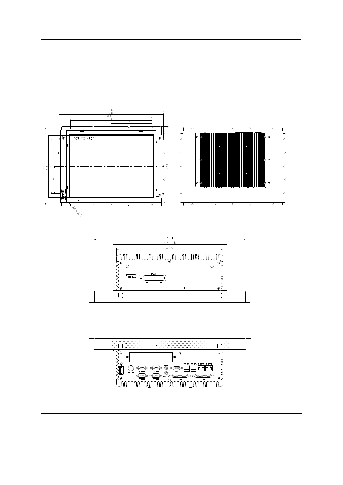
1-2. SYSTEM ILLUSTRATION
Front View Rear View
Top View
Bottom View
Unit: mm
2KHL+HMDÐ/3Ða
Chapter 1 Introduction
Page: 1-4
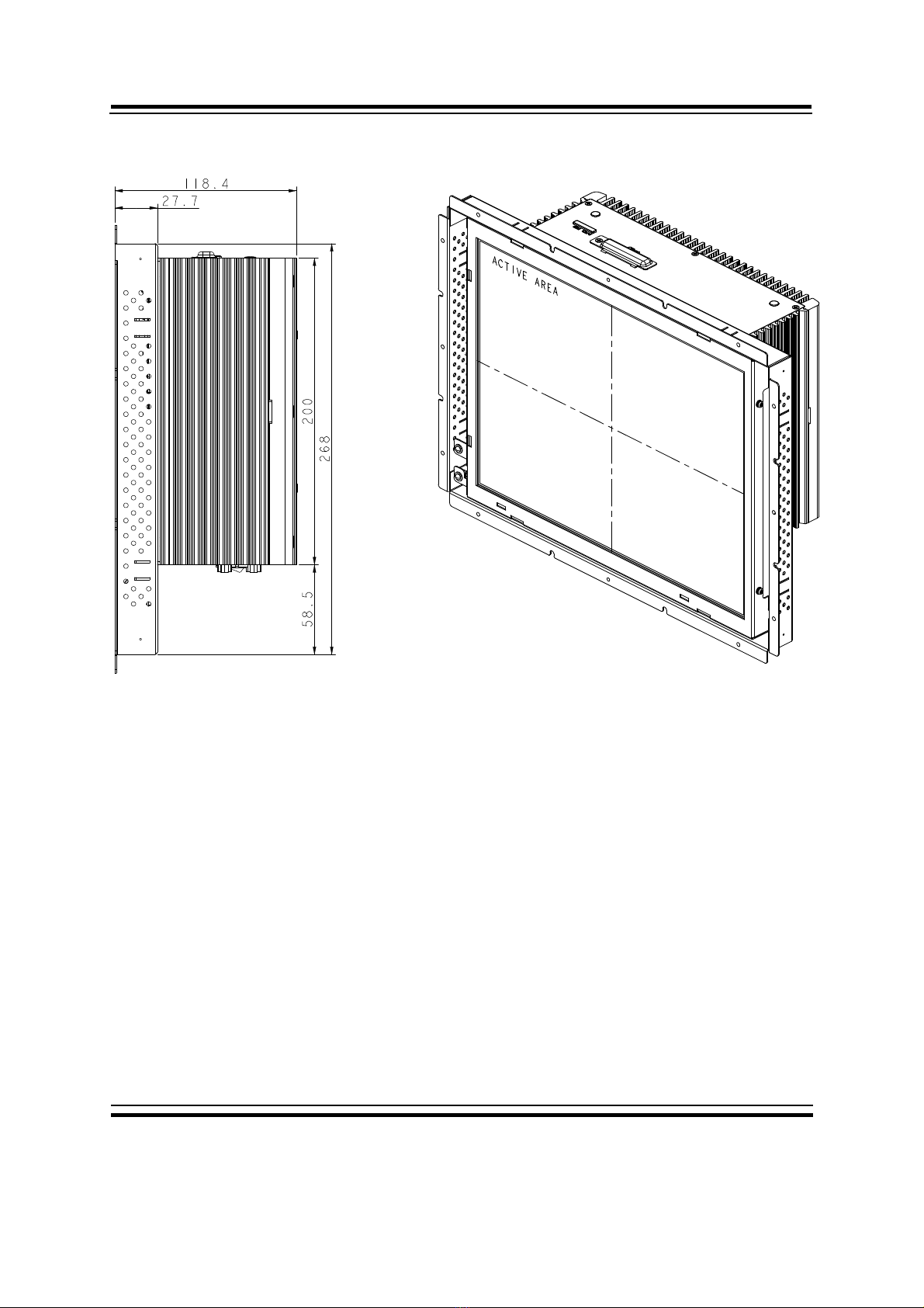
Side View Quarter View
Unit: mm
Este manual sirve para los siguientes modelos
3
Tabla de contenidos
Otros manuales de Panel táctil de TL Electronic

Manuales populares de Panel táctil de otras marcas


IBASE Technology
IBASE Technology ASTUT-152-RE1S Manual de usuario

YASKAWA
YASKAWA TP 610C Manual de usuario

B&R
B&R Power Panel C Series Manual de usuario

Beijer Electronics
Beijer Electronics X2 control Manual de usuario

AXIOMTEK
AXIOMTEK GOT321W-521 Manual de usuario

TRIDONIC.ATCO
TRIDONIC.ATCO x-touchBOX Manual de usuario


