Model 370 and 380 Series __________________________________________________________________Table of Contents
iv
Table of Contents
Section 1 - Installation and Start-up . . . . . . . . . . . . . .1 - 1
1.1 Incubator Components . . . . . . . . . . . . . . . . . . . . . . .1 - 1
1.2 Control Panel Keys, Displays and Indicators . . . . . .1 - 1
1.3 Operation of the Keypad . . . . . . . . . . . . . . . . . . . . .1 - 2
1.4 Displays . . . . . . . . . . . . . . . . . . . . . . . . . . . . . . . . .1 - 2
1.5 Installing the Incubator . . . . . . . . . . . . . . . . . . . . . .1 - 2
a. Choosing the Location . . . . . . . . . . . . . . . . . . . .1 - 2
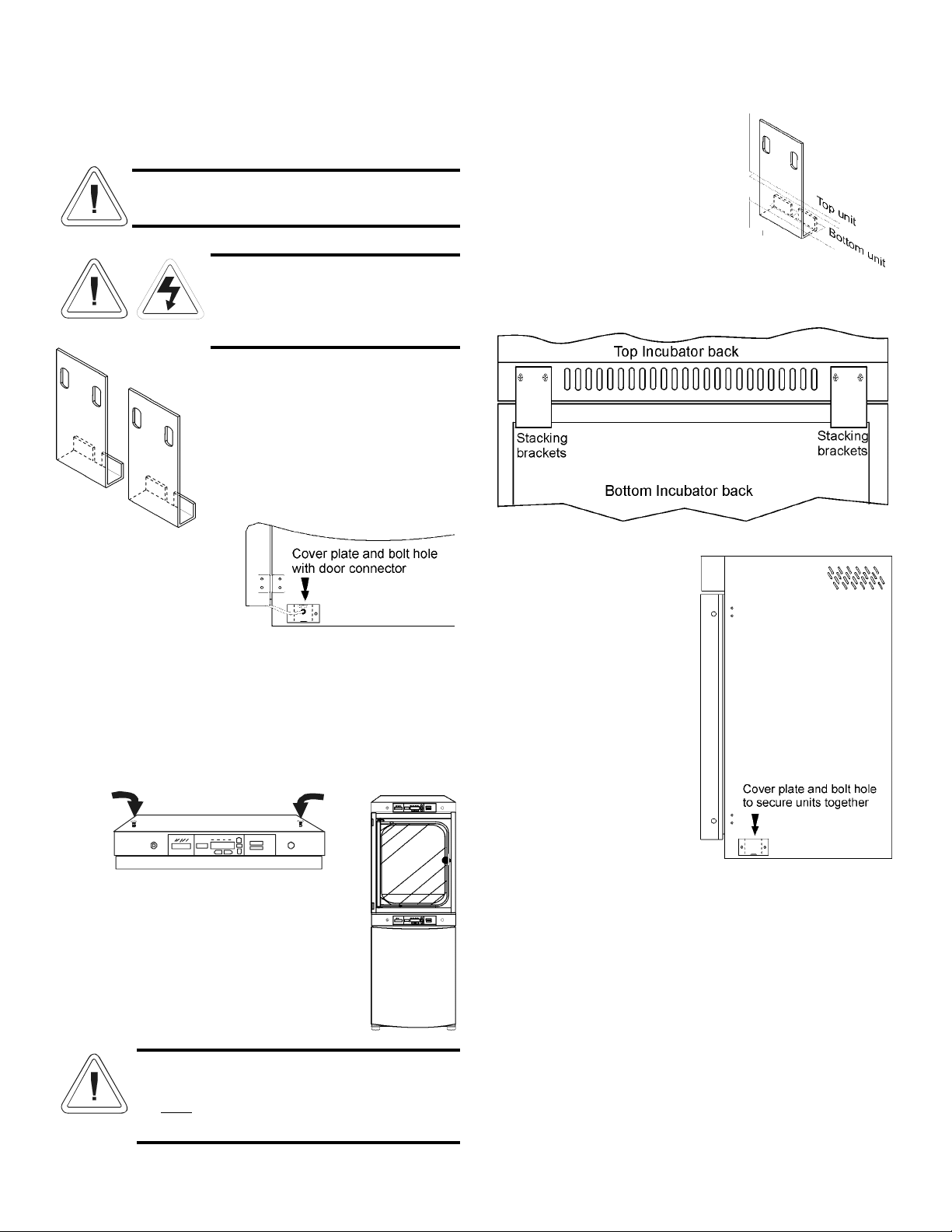
b. Stacking the Incubators . . . . . . . . . . . . . . . . . . .1 - 3
c. Preliminary Cleaning and Disinfecting . . . . . . . .1 - 4
d. Installing the Shelves . . . . . . . . . . . . . . . . . . . . .1 - 4
e. Installing the Access Port Filter and CO2Sensor Cover
Plate . . . . . . . . . . . . . . . . . . . . . . . . . . . . . . . . . .1 - 4
f. Installing the HEPA Filter . . . . . . . . . . . . . . . . . .1 - 4
g. Installing the Air Sample Filter . . . . . . . . . . . . . .1 - 5
h. Leveling the Unit . . . . . . . . . . . . . . . . . . . . . . . .1 - 5
i. Connecting the Unit to Electrical Power . . . . . . .1 - 5
j. Filling the Humidity Pan . . . . . . . . . . . . . . . . . . .1 - 5
k. Connecting the CO2Gas Supply . . . . . . . . . . . . .1 - 6
1.6 Incubator Start-Up . . . . . . . . . . . . . . . . . . . . . . . . . .1 - 6
a. Setting the Operating Temperature . . . . . . . . . . .1 - 6
b. Setting the Overtemp Setpoint . . . . . . . . . . . . . .1 - 6
c. Setting the CO2Setpoint . . . . . . . . . . . . . . . . . . .1 - 7
Section 2 - Calibration . . . . . . . . . . . . . . . . . . . . . . . . .2 - 1
2.1 Calibration Mode . . . . . . . . . . . . . . . . . . . . . . . . . . .2 - 1
a. Calibrating the Temperature . . . . . . . . . . . . . . . .2 - 1
b. Calibrating Thermal Conductivity CO2System . .2 - 1
c. Calibrating the Infrared CO2System . . . . . . . . . .2 - 1
d. Calibrating Relative Humidity . . . . . . . . . . . . . .2 - 2
Section 3 - Configuration . . . . . . . . . . . . . . . . . . . . . . .3 - 1
3.1 Configuration Mode . . . . . . . . . . . . . . . . . . . . . . . .3 - 1
a. Turning the Audible Alarm ON/OFF . . . . . . . . .3 - 1
b. New HEPA Filter . . . . . . . . . . . . . . . . . . . . . . . .3 - 1
c. Setting the REPLACE HEPA filter reminder . . .3 - 1
d. Setting an Access Code . . . . . . . . . . . . . . . . . . .3 - 1
e. Setting a Low Temp Alarm Limit . . . . . . . . . . . .3 - 1
f. Enabling Low Temp Alarm to Trip Contacts . . . .3 - 2
g. Setting a Low CO2Alarm Limit . . . . . . . . . . . . .3 - 2
h. Setting a High CO2Alarm Limit . . . . . . . . . . . . .3 - 2
i. Enabling CO2Alarms to Trip Contacts . . . . . . . .3 - 2
j. Setting New Zero Number for T/C CO2Sensors . .3 - 2
k. Setting New Span Number for T/C CO2Sensors .3 - 2
l. Setting a Low RH Alarm Limit . . . . . . . . . . . . . .3 - 3
m. Enabling RH Alarms to Trip Contacts . . . . . . . .3 - 3
n. Enabling Temp/RH to be Displayed . . . . . . . . . .3 - 3
o. Selecting a Primary Tank w/ Gas Guard Option .3 - 3
p. Enabling the Gas Guard System . . . . . . . . . . . . .3 - 3
q. Setting a RS485 Communications Address . . . . .3 - 3
Section 4 - Alarms . . . . . . . . . . . . . . . . . . . . . . . . . . . .4 - 1
4.1 Alarms . . . . . . . . . . . . . . . . . . . . . . . . . . . . . . . . . .4 - 1
4.2 Temperature Controller Failure . . . . . . . . . . . . . . . . .4 - 1
4.3 Sensor Fault Alarms . . . . . . . . . . . . . . . . . . . . . . . .4 - 1
Section 5 - Routine Maintenance . . . . . . . . . . . . . . . . .5 - 1
5.1 Disinfecting the Incubator Interior . . . . . . . . . . . . . .5 - 1
5.2 Cleaning the Cabinet Exterior . . . . . . . . . . . . . . . . . .5 - 1
5.3 Cleaning the Glass Doors . . . . . . . . . . . . . . . . . . . .5 - 1
5.4 Cleaning the Humidity Pan . . . . . . . . . . . . . . . . . . .5 - 2
5.5 Reversing the Door Swing . . . . . . . . . . . . . . . . . . . .5 - 2
5.6 HEPA Filter Maintenance . . . . . . . . . . . . . . . . . . . . .5 - 3
5.7 Replacing the Power Fuses . . . . . . . . . . . . . . . . . . .5 - 3
5.8 Replacing Air Sample Filter . . . . . . . . . . . . . . . . . .5 - 3
5.9 The Electronics Section . . . . . . . . . . . . . . . . . . . . .5 - 3
a. Major Components . . . . . . . . . . . . . . . . . . . . . . . .5 - 4
5.10 Sterilization Cycle . . . . . . . . . . . . . . . . . . . . . . . . .5 - 5
Section 6 - Factory Options . . . . . . . . . . . . . . . . . . . . .6 - 1
6.1 Connections to External Equipment . . . . . . . . . . . . .6 - 1
a. Connecting the Remote Alarm Contacts . . . . . . .6 - 1
b. Connecting the RS485 Interface . . . . . . . . . . . . .6 - 1
c. Connecting the Analog Output Boards . . . . . . . .6 - 1
6.2 CO2Gas Guard . . . . . . . . . . . . . . . . . . . . . . . . . . . . .6 - 2
a. Connecting the CO2Gas Supplies . . . . . . . . . . . .6 - 2
b. Activating the Gas Guard . . . . . . . . . . . . . . . . . .6 - 2
c. Operation of the CO2Gas Guard . . . . . . . . . . . . .6 - 3
6.3 Humidity Readout . . . . . . . . . . . . . . . . . . . . . . . . . .6 - 3
a. Factors Affecting Humidity Level in Chamber . .6 - 3
b. Accuracy of the Humidity Readout . . . . . . . . . . .6 - 3
Section 7 - Specifications . . . . . . . . . . . . . . . . . . . . . . . .7 -1
Section 8 - Spare Parts . . . . . . . . . . . . . . . . . . . . . . . . .8 - 1
Section 9 - Electrical Schematics . . . . . . . . . . . . . . . . .9 - 1
Section 10 - Warranty Information . . . . . . . . . . . . .10 - 1