Themis XV1 Series Manual de usuario
XV1
XV1
User
Manual
User
Manual
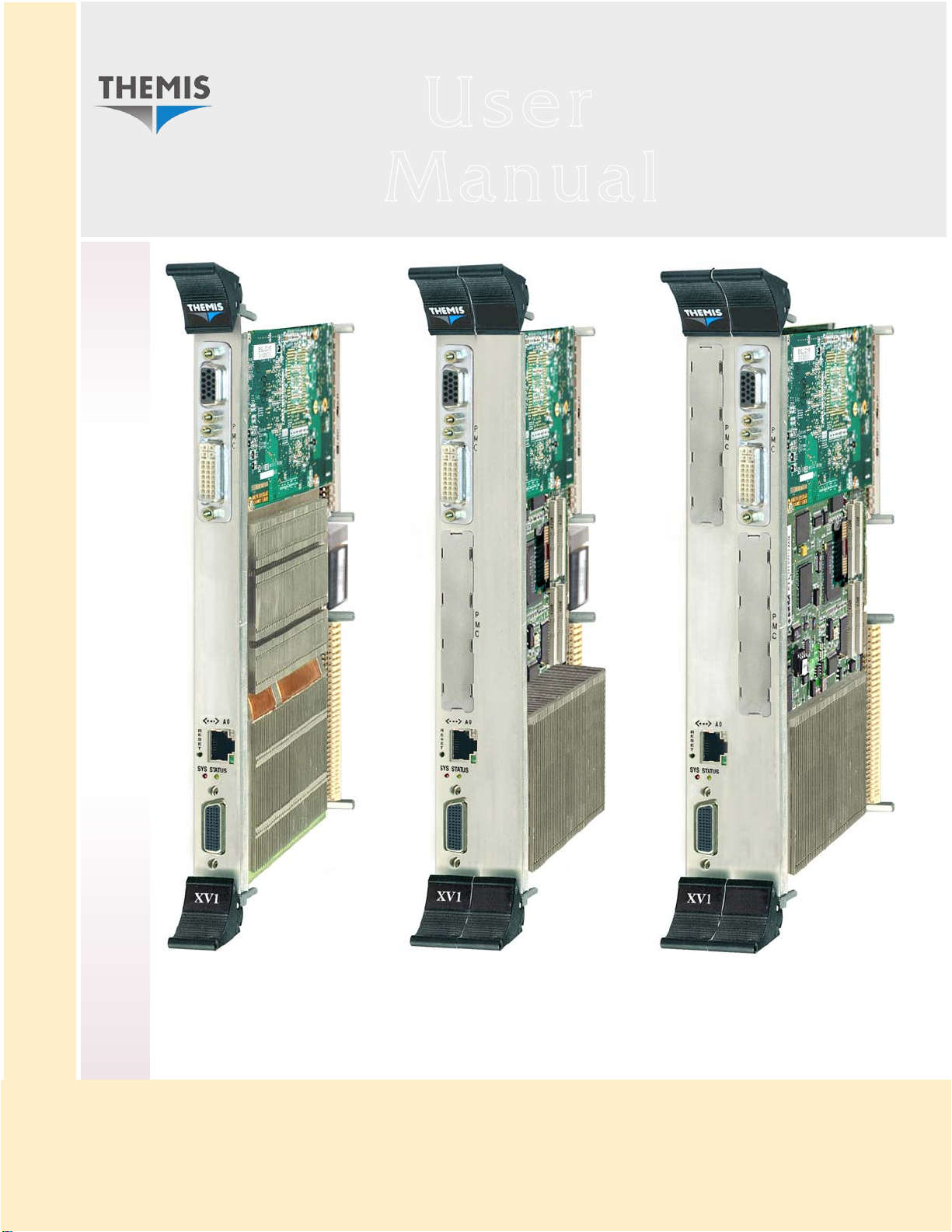
Intel Quad-Core Xeon CPU / Up to 2.13 GHz / 6RU VME64 Platform
1/2/3 PMC Slots / 1-Gigabit Ethernet / SATA II / SVGA / USB / IDE / Floppy / Audio

Intel Quad-Core Xeon CPU, VME64 Platform
XV1
XV1
Intel Quad-Core Xeon CPU, VME64 Platform
XV1
XV1
Intel Quad-Core Xeon CPU, VME64 Platform
XV1
XV1
Intel Quad-Core Xeon CPU, VME64 Platform
XV1
XV1
Intel Quad-Core Xeon CPU, VME64 Platform
XV1
XV1
Intel Quad-Core Xeon CPU, VME64 Platform
XV1
XV1
Intel Quad-Core Xeon CPU, VME64 Platform
XV1
XV1

Themis Computer—Rest of World
5 Rue Irene Joliot-Curie
38320 Eybens, France
Phone +33 476 14 77 80
Fax +33 476 14 77 89
Themis Computer—Americas and Pacific Rim
47200 Bayside Parkway
Fremont, CA 94538
Phone (510) 252-0870
Fax (510) 490-5529
World Wide Web http://www.themis.com
XV1HardwareManual
Version 1.0—June 2009

Copyright © 2009 Themis Computer, Inc.
ALL RIGHTS RESERVED. No part of this publication may be reproduced in any form, by
photocopy, microfilm, retrieval system, or by any other means now known or hereafter invented without
the prior written permission of Themis Computer.
The information in this publication has been carefully checked and is believed to be accurate. However,
Themis Computer assumes no responsibility for inaccuracies. Themis Computer retains the right to
make changes to this publication at any time without prior notice. Themis Computer does not assume
any liability arising from the application or use of this publication or the product(s) described herein.
RESTRICTED RIGHTS LEGEND: Use, duplication, or disclosure by the United States Government
is subject to the restrictions set forth in DFARS 252.227-7013 (c)(1)(ii) and FAR 52.227-19.
TRADEMARKS
Themis®is a registered trademark of Themis Computer, Inc.
XV1™ is a trademark of Themis Computer, Inc.
Intel®is a registered trademark of Intel Corporation.
Xeon™ and Core™ are trademarks of Intel Corporation.
Tsi148™ is a trademark of the Tundra Semiconductor Corporation.
All other trademarks or registered trademarks used in this publication are the property of their
respective owners.
XV1 Hardware Manual, Version 1.0
June 2009
Part Number: 116704-022
Themis Customer Support
North America, South America, and Pacific Rim
Telephone: 510-252-0870
Fax: 510-490-5529
E-mail: support@themis.com
Web Site: http://www.themis.com

iii
Themis Computer
XV1 Hardware Manual
VersionRevisionHistory
Version 1.0............................................................................................June 2009

iv Themis Computer
XV1 Hardware Manual

v
Themis Computer
Table of Contents
How to Use This Manual .................................................................................................... xiii
1. XV1 Installation ............................................................................................................ 1-1
1.1 Determine Board Type ........................................................................................... 1-1
1.2 Check Configurations ............................................................................................ 1-2
1.3 Install the Paddle Board ........................................................................................ 1-2
1.4 Attach Front-Panel I/O Cables ............................................................................... 1-5
1.4.1 Gigabit Ethernet Port C .............................................................................. 1-5
1.4.2 Multiple-I/O Connector Ports .................................................................... 1-5
1.5 Attach Paddle-Board Cables .................................................................................. 1-6
1.5.1 Serial Ports COM1 and COM2 .................................................................. 1-6
1.5.2 PS/2 Keyboard & Mouse ........................................................................... 1-6
1.5.3 USB Ports 2, 3, 4, and 5 ............................................................................. 1-6
1.5.4 SVGA Video Port ...................................................................................... 1-6
1.5.5 SATA Ports 3, 4, and 5 .............................................................................. 1-7
1.5.6 Stereo Audio I/O Connectors ..................................................................... 1-7
1.5.7 Auxiliary +12V/+5V Power Connectors ................................................... 1-7
1.5.7.1 +12V Power Connector .............................................................. 1-7
1.5.7.2 +5V Power Connectors ............................................................... 1-7
1.6 Daisy-Chain Jumper Settings ................................................................................. 1-8
1.7 TOD/NVRAM Battery .......................................................................................... 1-8
2. XV1 Features and Specifications ................................................................................. 2-1
2.1 Baseboard ............................................................................................................... 2-1
2.2 PMC/XMC Cards .................................................................................................. 2-4
2.3 Paddle Board .......................................................................................................... 2-4
2.4 PMC/XMC Carrier Boards ................................................................................... 2-5
2.5 I/O-Expansion Board ............................................................................................. 2-5
2.6 System Specifications ............................................................................................ 2-6

vi Themis Computer
XV1 Hardware Manual
2.6.1 Processor and Memory Subsystems .......................................................... 2-6
2.6.2 Operating Systems ..................................................................................... 2-6
2.6.3 I/O Subsystem ............................................................................................ 2-7
2.6.4 Auxiliary Functions ................................................................................... 2-8
2.7 Environmental Specifications ............................................................................... 2-9
2.8 Regulatory Compliance ......................................................................................... 2-9
2.9 Typical Power Requirements ............................................................................... 2-10
3. Hardware Overview ...................................................................................................... 3-1
3.1 Baseboard ............................................................................................................... 3-1
3.1.1 Intel 5408 Quad-Core LV Xeon Processor ................................................ 3-1
3.1.2 Intel 5100 Memory Controller Hub (MCH) .............................................. 3-2
3.1.3 Intel 82801 I/O Controller Hub (ICH) ....................................................... 3-2
3.1.4 82571EB Dual Gigabit Ethernet Controller ............................................... 3-3
3.1.5 SCH5027 Super I/O Controller .................................................................. 3-3
3.1.6 Tundra Tsi148 PCI/X-to-VME Bridge ...................................................... 3-4
3.1.7 Programmable Logic .................................................................................. 3-4
3.1.8 BIOS Flash Memory .................................................................................. 3-4
3.2 PMC/XMC Carrier Boards ................................................................................... 3-5
3.3 I/O-Expansion Board ............................................................................................. 3-5
Appendix A. Connector Pinouts and Signal Descriptions ............................................ A-1
A.1 XV1 Rear Connectors ........................................................................................... A-1
A.1.1 VME P1 Connector ................................................................................... A-1
A.1.2 VME P2 Connector ................................................................................... A-3
A.2 XV1 Front-Panel Connectors ................................................................................ A-5
A.2.1 Gigabit Ethernet (GbE) Port C .................................................................. A-5
A.2.2 Multiple-I/O Connector ............................................................................ A-6
A.2.2.1 Serial Ports COM1 & COM2 ..................................................... A-7
A.2.2.2 SATA3 Port ............................................................................... A-7
A.2.2.3 USB Ports USB0 & USB1 ......................................................... A-8
A.2.2.4 VGA Graphics Port .................................................................... A-8
A.3 Push-Button RESET ............................................................................................. A-8
A.4 XV1 PMC Module Card Connectors .................................................................... A-8
A.4.1 PMC Module Connector J21 / J11 ............................................................ A-9

vii
Themis Computer
Table of Contents
A.4.2 PMC Module Connector J22 / J12 .......................................................... A-10
A.4.3 PMC Module Connector J23 .................................................................. A-11
A.4.4 PMC Module Connector J24 .................................................................. A-12
A.5 XV1 P2 Paddle Board ......................................................................................... A-12
A.5.1 Serial COM1 and COM2 Connectors ..................................................... A-12
A.5.2 DIN-8 PS/2 Keyboard/Mouse Connector ............................................... A-13
A.5.3 USB Ports USB2 / USB3 and USB4 / USB5 ......................................... A-14
A.5.4 SVGA Monitor Port (5-Row VME Backplane Only) ............................ A-15
A.5.5 SATA Ports 3, 4, and 5 ........................................................................... A-16
A.5.6 Auxiliary +12-Volt/+5-Volt Power Connectors ..................................... A-17
A.5.6.1 Auxiliary +12-Volt Power Connector ...................................... A-17
A.5.6.2 Auxiliary +5-Volt Power Connectors ...................................... A-17
A.5.7 Stereo Audio In/Out Connectors ............................................................. A-18
A.5.8 Gigabit Ethernet A and Ethernet B
(5-Row VME Backplane Only) A-18
Appendix B. Jumper Pins and Solder Beads ..................................................................B-1
B.1 Field-Configurable Jumper Pins ............................................................................B-1
B.1.1 XV1 Jumper Pins .......................................................................................B-1
B.1.2 Memory Module Jumper Pins ....................................................................B-2
B.1.3 XV1 Paddle-Board Jumper Pins ................................................................B-4
B.2 Factory-Configurable Solder Beads .......................................................................B-4
B.2.1 XV1 Solder Beads .....................................................................................B-4
B.2.2 Memory Module Solder Beads ..................................................................B-8
B.2.3 XV1 Paddle-Board Solder Beads ..............................................................B-8
Appendix C. Front-Panel I/O Connections and LEDs ...................................................C-1
C.1 Introduction ............................................................................................................C-1
C.1.1 Front-Panel Dimensions ............................................................................C-1
C.1.2 Injector/Ejector Handles ............................................................................C-2
C.1.2.1 VME64-type Handles .................................................................C-2
C.1.2.2 Legacy-VME Handles ................................................................C-2
C.2 XV1 Front Panels ...................................................................................................C-3
C.2.1 Multiple-I/O Connector .............................................................................C-3
C.2.2 XV1/1—1 PMC/XMC Module ...............................................................C-4
C.2.3 XV1/2—2 PMC/XMC Modules ...............................................................C-5

viii Themis Computer
XV1 Hardware Manual
C.2.4 XV1/3—3 PMC/XMC Modules ...............................................................C-6
C.3 LEDs ......................................................................................................................C-7
Appendix D. Board Component and Connector Diagrams .......................................... D-1
D.1 XV1 Baseboard ..................................................................................................... D-1
D.2 P2 Paddle Board .................................................................................................... D-1
Appendix E. VME Slot Configurations ...........................................................................E-1
Index...............................................................................................................................Index-1
Reader Comment Card
Este manual sirve para los siguientes modelos
3
Tabla de contenidos


