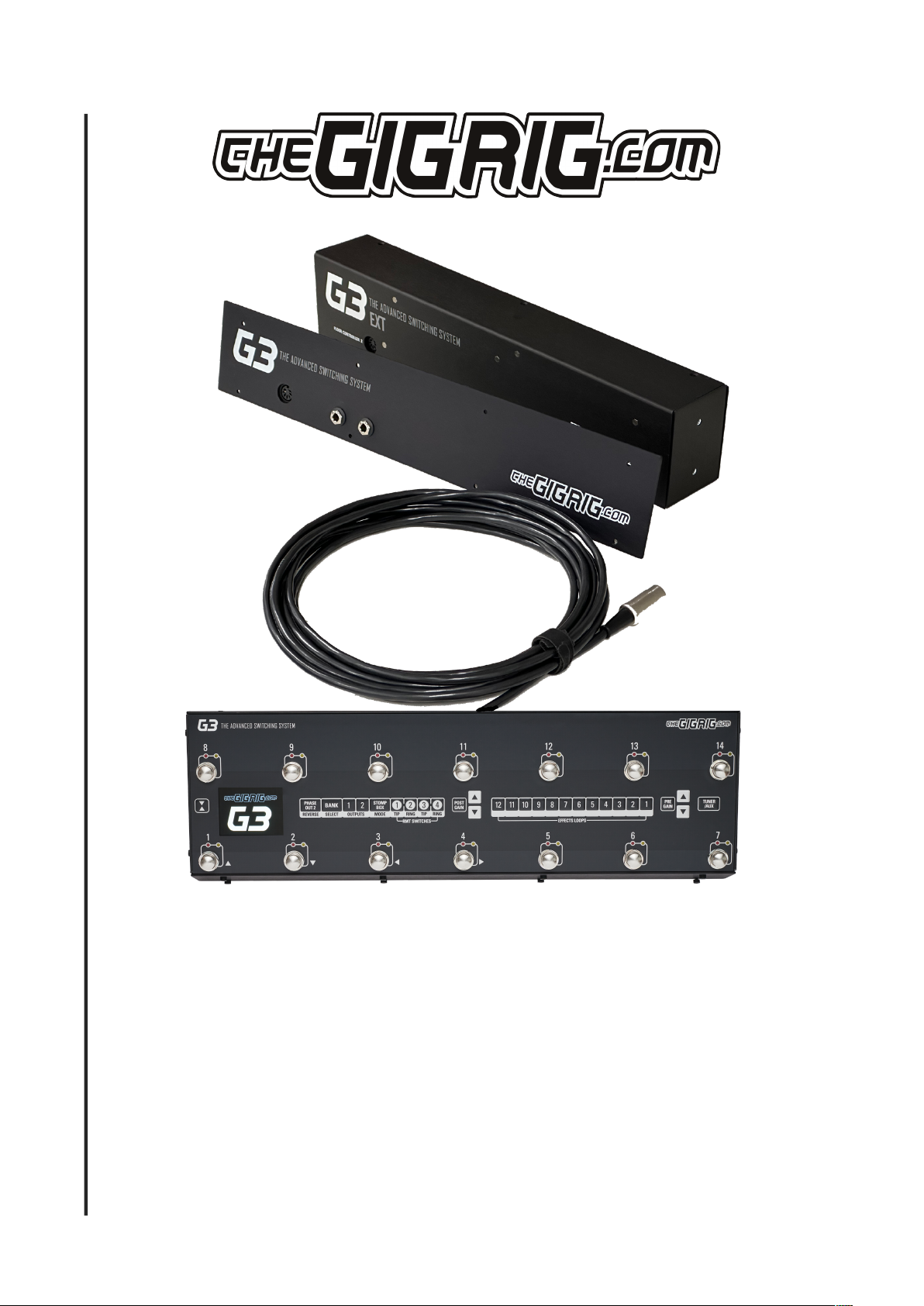
THEGIGRIG ABY BABY USER MANUAL
Assembly
Watch the associated video with this manual to understand how to assemble the Ext Kit
The assembly video is here - https://youtu.be/sRbKSpte9Kk
It’s important to adhere to every step of these instructions in order to ensure your G3 Ext Kit performs flawlessly. Timestamps below
correspond to the assembly video
0:00 Intro
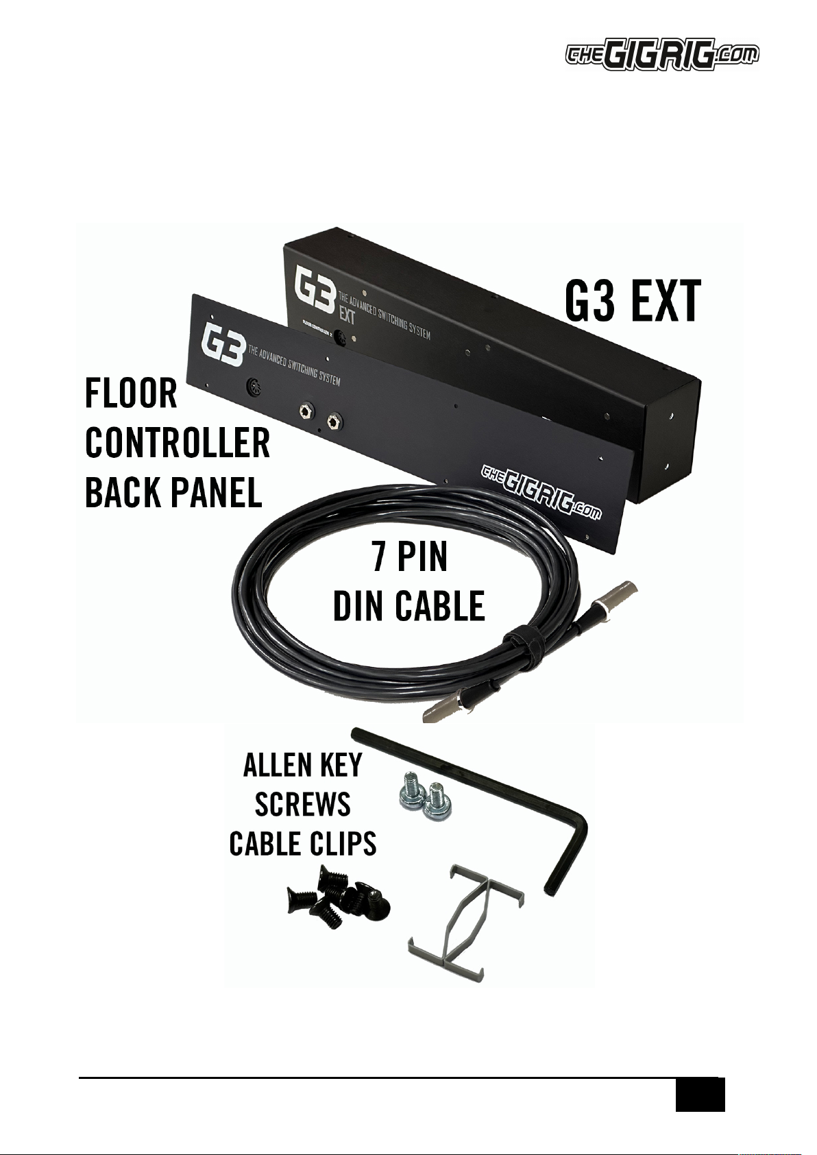
0:23 Unboxing, what’s included
0:44 Undo the 8 hex screws on the front panel
1:06 Undo the 2 hex screws on each side of G3
1:11 Undo the top row of 4 hex screws on the back of G3
1:21 Lift out the top panel
1:30 Undo the ribbon cable that connects the top panel to the motherboard. Undo the cable clip before removing the cable
1:45 Undo the clip on the other end of the cable and remove from the motherboard
1:54 Remove the red/black tuner cable from the motherboard
2:00 Tilt unit forward and remove bottom row of 4 hex screws from the back panel
2:16 Disconnect the back panel from the base by disconnecting the last 2 ribbon cables from the mother board
2:52 Remove the motherboard from the G3 base by undoing the 4 screws
3:16 Separate the back board from the back panel metalwork by undoing all the nuts on the back panel. 13mm socket, if required
3:45 Set aside the back panel metal plate
3:56 Connect back board to Ext kit back panel
4:00 Fold large ribbon cable as shown on the video
4:30 Extend the 2 small ribbon cables on the motherboard away from the metalwork and insert the back circuit board
4:50 Metal washers on nuts are used from Input/Aux to Send/Return loop 12 (left hand side)
4:50 Black plastic insulation washers and nuts from Outputs to Remote Switches (right hand side)
5:40 Attach the motherboard to the front panel of the Ext Kit using the screws from the G3 base plate
6:25 Connect ribbon cables to the motherboard in the following order;
6:33 Connect the black/red tuner cable to motherboard
6:40 Connect the small ribbon cable that sits underneath the large ribbon cable, ensuring that the cable clip is in place
6:55 Connect the other small ribbon cable by bringing the front panel closer to the motherboard. Finish with cable clip
7:05 Connect the large ribbon cable and finish with clip
7:20 Connect the front and back sections with the screws provided
8:00 Assemble the floor controller section
8:10 Connect the floor controller back panel to the base of G3 by screwing the expression pedal circuit board to the base
8:30 Using 4 hex screws connect the back panel to G3 base
8:45 Connect the top/footswitch board ribbon cable finishing with the clip
9:00 Connect the front/footswitch panel to G3 floor controller base with hex screws
9:40 Attach front panel to floor controller
10:00 Connect EXT KIT to the Floor Controller with 7 pin din cable provided
10:05 Apply power to the EXT KIT
FAQ’s
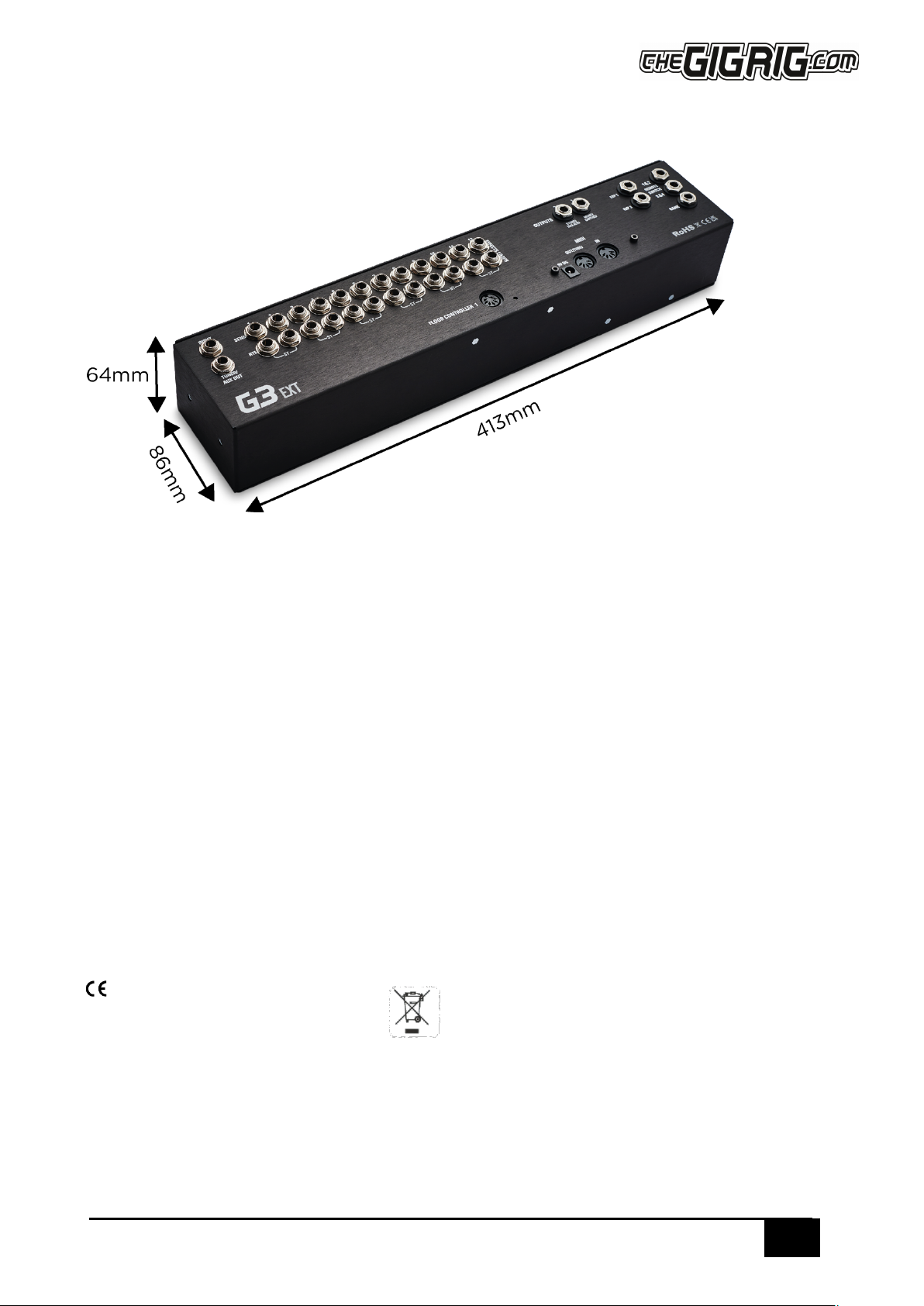
Q. How do I connect this to a rack?
A. The Ext Kit fits on to a flat base rack drawer but the base of the rack needs to have an internal measurement of at least 413mm
Q. Can I control the EXT KIT from a MIDI controller?
A. No. The 7 pin DIN connector doesn’t use MIDI to communicate between the two sections, it uses something else entirely, so trying
to use only the EXT KIT with a different MIDI controller won’t work. You can connect MIDI to the MIDI IN on the floor controller unit
and use it that way, but not directly to the EXT KIT