TeraBee TeraRanger Evo Manual de usuario

User Manual for TeraRanger Evo
single point distance sensors and
backboards
TeraRanger
Evo 60m
TeraRanger
Evo 40m
TeraRanger
Evo 15m
TeraRanger
Evo 3m
USB
backboard
I2C
backboard
Technical support: terabee.com/support/
Sales and commercial support: [email protected]

Table of contents
1. Introduction 3
2. Mechanical integration 4
2.1. Mechanical design 5
2.2. Sensor handling during system assembly 5
3. USB backboard use 6
3.1. Graphical User Interface (version 1.0.3) 6
3.1.1. Prerequisites 6
3.1.2. Basic operation 6
3.1.3. Firmware upgrade 7
3.2. Connecting the TeraRanger Evo to a host computer 8
4. I2C/UART backboard use 9
4.1. I2C/UART interface 9
4.1.1. Backboard LEDs 10
4.1.2. Electrical characteristics 10
4.2. I2C communication 11
4.2.1. I2C protocol information 11
4.2.2. I2C commands 12
4.3. UART communication 12
4.3.1. UART protocol information 12
4.3.2. Commands 13
4.3.3. UART output format 13
5. Declaration of conformity 15
Copyright © Terabee 2023
Terabee, 90 rue Henri Fabre
01630 Saint-Genis-Pouilly, France (next to CERN)
TeraRanger Evo Family
User Manual
2/15

1. Introduction
The purpose of this document is to give guidelines for use and integration of the
following TeraRanger Evo distance sensors:
1. TeraRanger Evo 60m
2. TeraRanger Evo 40m
3. TeraRanger Evo 15m
4. TeraRanger Evo 3m
with (a) UART/I2C backboard, and/or (b) USB backboard using these standard
communication interfaces. Please consult the following table for visual differences
between TeraRanger Evo sensors.
Product
Visualization
Hardware
TeraRanger Evo 60m
Black optical sensor module
TeraRanger Evo 40m
A blue sticker is applied on the
sensor
TeraRanger Evo 15m
A green sticker is applied on the
sensor
TeraRanger Evo 3m
Sensor’s lens surface is flat,
unlike Evo 60m, 40m, 15m
Copyright © Terabee 2023
Terabee, 90 rue Henri Fabre
01630 Saint-Genis-Pouilly, France (next to CERN)
TeraRanger Evo Family
User Manual
3/15

2. Mechanical integration
The mechanical design of the main sensor module (black) allows easy assembly to its
backboard (yellow) using a simple ‘clip-in’ technique (when you clip the two together,
ensure there is no visible gap between the black and yellow parts). The yellow
backboard has two mounting holes for final installation.
When choosing a place for mounting, please consider the following recommendations:
●Choose a place which is in accordance with the optical constraints listed below
●Mounting close to sources of heat or strong electromagnetic fields can decrease
the sensing performance
●Do not mount anything directly in front of the sensor or in a cone of
approximately +/-15° around the central optical axis of the sensor
●Within the first meter from the sensor, avoid objects with high surface reflectivity
in a cone of approximately +/-45° around the central optical axis of the sensor
●It is better to avoid having other sources of Continuous Wave or modulated IR
light close to the sensor
●Please consider that dust, dirt and condensation can affect the sensor
performance
●It is not advised to add an additional cover in front of the sensor
●Drone rotor blades, or other environments with flickering (‘chopped’) ambient
light in the field of view can affect sensors’ readings
Copyright © Terabee 2023
Terabee, 90 rue Henri Fabre
01630 Saint-Genis-Pouilly, France (next to CERN)
TeraRanger Evo Family
User Manual
4/15

2.1. Mechanical design
2.2. Sensor handling during system assembly
During assembly and integration, please observe all common ESD precautions. All
optical surfaces (sensor front) should be kept clean and free from contact with
chemicals.
Copyright © Terabee 2023
Terabee, 90 rue Henri Fabre
01630 Saint-Genis-Pouilly, France (next to CERN)
TeraRanger Evo Family
User Manual
5/15
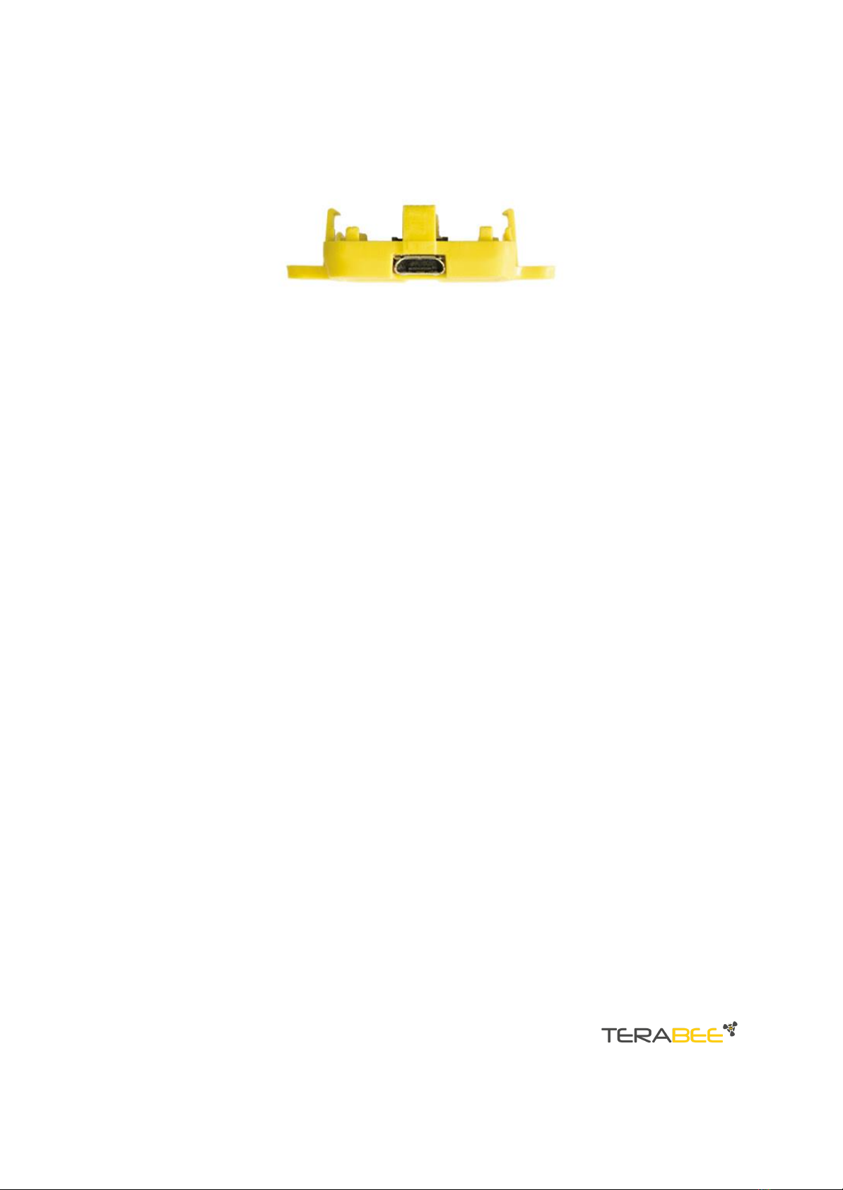
3. USB backboard use
The USB backboard comes with a standard Micro-USB connector.
3.1. Graphical User Interface (version 1.0.3)
A free Graphical User Interface (GUI) is available, providing an easy way to visualize the
data from your TeraRanger Evo. This is useful for demonstration, testing purposes and
checking some of the basic parameters of the sensor. It also provides a way to easily
upgrade the firmware running on the device.
The GUI is available on the “Downloads” section of the TeraRanger Evo product pages.
Please ensure you are using GUI version 1.0.3 or later.
If you need to identify which TeraRanger Evo sensor is currently connected, in the GUI
select, Help > About.
3.1.1. Prerequisites
For usage on Windows 7 and Windows 8, please download the Virtual COM Port driver
from http://www.st.com/en/development-tools/stsw-stm32102.html and follow the
”ReadMe file” instructions given by the installer . After successful installation, unplug
the interface for a few seconds, and plug it back in. The virtual COM port should now be
available on your PC.
Users of Windows 10 do not need to download this driver as the built in Windows driver
is recommended.
3.1.2. Basic operation
Make sure your TeraRanger Evo is connected to a USB port on your computer. In the
GUI select File > Connect. You should immediately see a distance reading in millimetres
and the status should change to ‘Connected’.
Copyright © Terabee 2023
Terabee, 90 rue Henri Fabre
01630 Saint-Genis-Pouilly, France (next to CERN)
TeraRanger Evo Family
User Manual
6/15

3.1.3. Firmware upgrade
The current firmware version on your TeraRanger Evo can be found by selecting Help >
About in the graphical user interface. It is possible to upgrade the firmware running on
your device if a new firmware version is made available on the Terabee website.
Please note the Upgrade Firmware feature is only supported on Windows 7, 8 and 10.
Please carefully follow the steps outlined below to avoid permanently disabling your
device.
●Install the latest version of the TeraRanger Evo GUI on your computer
●Download the latest firmware file from the Terabee website
●In the GUI Select File > Connect and then File > Upgrade Firmware
●You will be presented with a dialog window asking you to confirm your choice
●After confirming your choice, a new dialog window will present you with
instructions on selecting the firmware file and launching the upgrade process,
read the instructions carefully.
●Press ‘Select File’ and select the new firmware file with Windows File Explorer
●Press ‘Upgrade’ and wait until the operation finishes
●Close the Upgrade dialog box
Copyright © Terabee 2023
Terabee, 90 rue Henri Fabre
01630 Saint-Genis-Pouilly, France (next to CERN)
TeraRanger Evo Family
User Manual
7/15

3.2. Connecting the TeraRanger Evo to a host computer
TeraRanger Evo can interact as a virtual COM port using the following configuration:
115200 bit/s, 8 data bits, no parity bit and one stop bit.
In Windows you can also use any terminal emulation software of your choosing,
however we suggest you use HTerm (http://www.der-hammer.info/terminal/). Extract
the downloaded zip file to the folder of your choice, open it and double click on the
“HTerm.exe” document.
Connect the TeraRanger Evo to your computer and select the corresponding USB port
(click “R” button to refresh the port list). Select values for the following fields: (1)
Baudrate, (2) Data Bits, (3) Parity, (4) Stop Bits. For easier readings, select the “LF” option
for “Newline at” tab. See Figure below for visual instructions.
Once you have selected the USB port and required values, click on the “Connect” button.
The data will now appear in the “Received data” box (Figure below).
To communicate with the terminal emulation software, you need to send a command in
hexadecimal via the “Type” box. First check the “Hex” checkbox and choose the “HEX”
Type. The figure above shows an example of the command which allows data to be
shown in TEXT mode.
Copyright © Terabee 2023
Terabee, 90 rue Henri Fabre
01630 Saint-Genis-Pouilly, France (next to CERN)
TeraRanger Evo Family
User Manual
8/15

4. I2C/UART backboard use
4.1. I2C/UART interface
The TeraRanger Evo can be controlled through I2C or UART interfaces. It uses a single 9
pin Hirose DF13 connector for interfacing to the host system. The mating connector is a
Hirose DF13-9S-1.25C with crimping contacts DF13-2630SCF (tin) or DF13-2630SCFA
(gold). Please consider the mechanical stability of the mated connectors and avoid any
kind of excess force on the connector (during installation and once integrated) and
follow the recommendations in the Hirose DF13 series datasheet (available here:
https://www.hirose.com/product/en/products/DF13) to ensure a reliable connection.
The table below provides an overview of the pin out of the DF13 connector:
Pin out and description (According to DF13 datasheet)
Pin
Designator
Description
1
Tx
UART transmit output. 3.3 V logic
2
Rx
UART receive input. 3.3 V logic
3
GND
Power supply and interface ground
4
SDA
I2C serial data line. 3.3 V logic
5
SCL
I2C serial clock line. 3.3 V logic
6
rfu
RESERVED FOR FUTURE USE
7
5V
+5V supply input
8
GND
Power supply and interface ground
9
rfu
RESERVED FOR FUTURE USE
Copyright © Terabee 2023
Terabee, 90 rue Henri Fabre
01630 Saint-Genis-Pouilly, France (next to CERN)
TeraRanger Evo Family
User Manual
9/15

4.1.1. Backboard LEDs
Five LEDs are mounted to give visual feedback on the sensor. Table below lists the
functionality of each LED:
LED
Description
PWR (orange)
Power indicator, on when 5 V connected
Rx/Tx (red/green)
UART receive and transmit indicators
LED 0 / LED 1
For internal use only
4.1.2. Electrical characteristics
DC electrical characteristics
Parameter
Sensor
Minimum
Maximum
Power supply
Voltage input (V)
Current
consumption (mA)
Evo 60m
4.75 V
90 mA
5.25 V
330 mA
Evo 600Hz
4.75 V
95 mA
5.25 V
190 mA
Evo 3m
4.75 V
70 mA
5.25 V
250 mA
Interface logic
levels
(referenced to
+3V3)
LOW
HIGH
-
2.3
1
-
*Value recorded while reading a target at 2m distance. NB: this value depends on
ambient conditions, distance and target reflectivity
Copyright © Terabee 2023
Terabee, 90 rue Henri Fabre
01630 Saint-Genis-Pouilly, France (next to CERN)
TeraRanger Evo Family
User Manual
10/15
Otros manuales para TeraRanger Evo
5
Este manual sirve para los siguientes modelos
3
Tabla de contenidos
Otros manuales de Accesorios de TeraBee

TeraBee
TeraBee TeraRanger Evo 64px Manual de usuario

TeraBee
TeraBee TeraRanger One Manual de usuario

TeraBee
TeraBee TeraRanger Neo ES Manual de usuario

TeraBee
TeraBee ND-TOF-1 Manual de usuario

TeraBee
TeraBee TeraRanger Evo Thermal series Manual de usuario

TeraBee
TeraBee IND-TOF-1 Manual de usuario

TeraBee
TeraBee TeraRanger Multiflex Manual de usuario

TeraBee
TeraBee TeraRanger Evo Series Manual de usuario

TeraBee
TeraBee IND-TOF-1 Manual de usuario

TeraBee
TeraBee TeraRanger Evo Manual de usuario


