Tenveo ALL-IN-ONE Manual de usuario

ALL-IN-ONE
Video Conference System
Version V5.2(English)
Add.: Rm 719-720, Block B, Tianhui
building, No 106, Yousong Rd, Lon-
ghua Dist, Shenzhen, China.
E-mail: [email protected]
Mobile: +86-18929337105
Add.: Rm 2302, Block A, Zhongdeng
Wenjing building, Fengcheng 9th Rd,
Weiyang Dist, Xi'an, China.
Tel: +86-29-81318040
Shenzhen Tenveo Video Technology Co,.ltd
Headquarter Xi'an Branch
www.tenveo.com/en
(ShenZhen)
3C
12
POWER STANDBY
R

Attention
This manual introduces the functions, installation and operations
of Tenveo All-In-One Video Conferencing System.
To prevent damage to this product or any product connected
to it, this product can only be used within the specified range.
1.1 Do not expose the product to rain or moisture.
1.2 To prevent the risk of electric shock, do not open the case.
Installation and maintenance should only be carried out by qualifi-
ed technicians.
1.3 Do not use the product beyond the specified temperature,
humidity or power supply specifications.
1.4 Wipe it with a soft, dry cloth when cleaning the camera le-
ns. Wipe it gently with a mild detergent if needed. Do not use str-
ong or corrosive detergents to avoid scratching the lens and affe-
cting the image.
1.How to Use
Installation and use of this product must strictly comply with l-
ocal electrical safety standards.
2.Electrical Safety
Avoid damage to the product caused by heavy pressure, stro-
ng vibration or immersion during transportation, storage and inst-
allation.
3.Handle with care
4.1 Do not rotate the camera head violently, otherwise it may
cause mechanical failure;
4.2 This product should be placed on a stable desktop or oth-
er horizontal surface. Do not install the product obliquely, otherw-
ise it may display inclined image;
4.3 Housing of this product is made of organic materials. Do
not expose it to any liquid, gas or solids which may corrode the shell;
4.4 Ensure there are no obstacles within rotation range of the
holder;
4.5 Do not power on before completing installation.
4.Install with Caution

Product Overview .............................. 2
Keys Operation Description ..............................
Connection Description .............................. 5-6
About Bluetooth Pairing .............................. 6
2.1 Speakerphone
Packing Contents .............................. 1
2.2 HD PTZ Camera
3.1 About Remote Control
3.2 About Speakerphone
Contents
Technical Specifications
Copyright Statement ............................. 10
Warranty
2
2
3
4
..............................
..............................
2.3 Hub 3
..............................
..............................
..............................
3
............................. 10
............................. 8-9
Indicator Status
About Presets ............................. 6
The Installation And Use Of
Expansion Mics(Optional) ............................. 7
............................. 6

1.Packing Contents
1
1
3
5
7
2
4
6
8Manual
1.Speakerphone
2.HD ptz camera
3.Hub
4.Remote controller
5.5m din6 cable * 2 pcs
6.3m usb cable *1 pcs
7.Power adapter
8.Manual
POWER STANDBYR
OK
21
-+
1
3C
2
+
-

2.Product Overview
2
2.1 Speakerphone
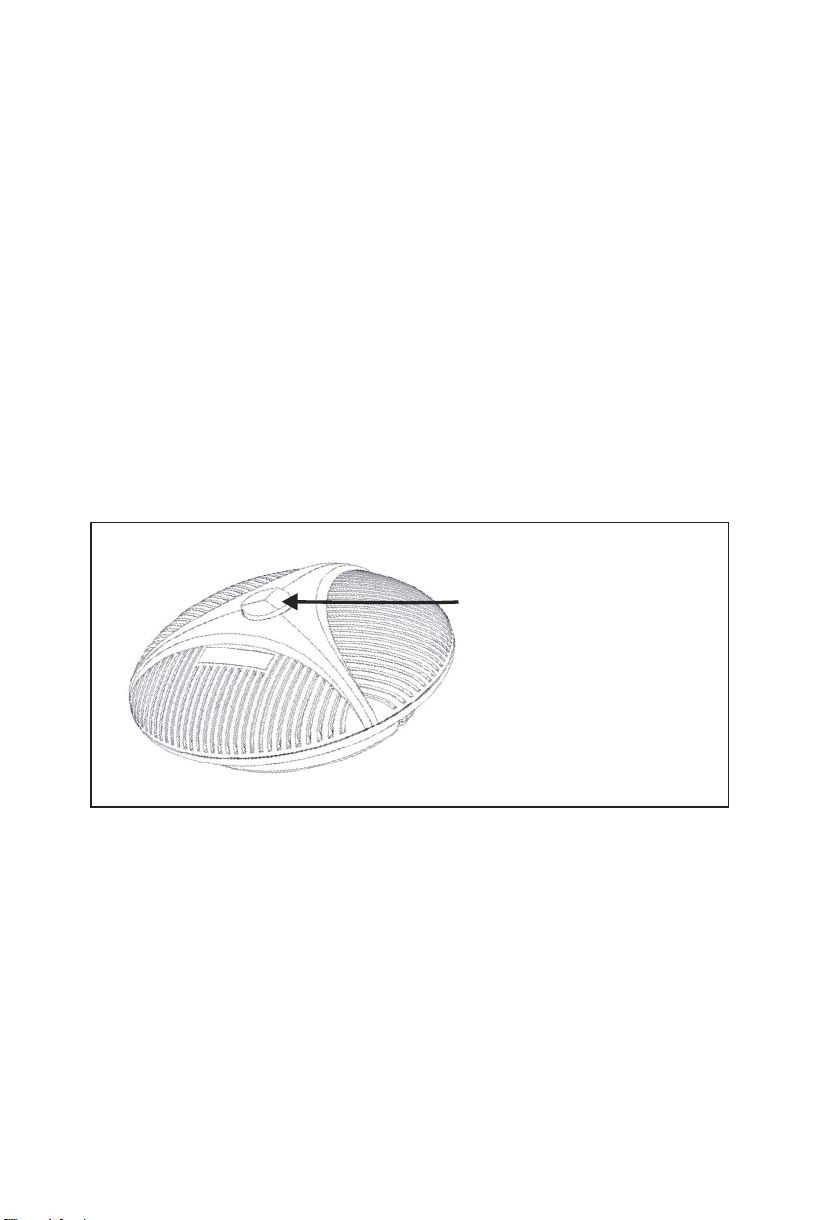
2.2 HD PTZ Camera
1.Optional expansion microphone port 1
2.Optional expansion microphone port 2
3.Din6 cable port
4.Led indicator
5.Bluetooth/power indicator
6.Function keys
7.Volume indicator
12 3
4
3C
12
5
67
1.Lens 2.Pan&Tilt 3.Standby indicator
4.IR remote indicator
5.Power indicator
6.Din6 cable slot
②
③
①
④
⑤
POWER STANDBYR
⑥

3.Keys Description
2.3 Hub
3.1 About Remote control
3
1. DIN6 Cable slot 2. DIN6 Cable slot
3. USB slot
5. Power switch
7. Screw holes 8. Wire slot
1: Volume down
2: Volume up
3: Camera pan/tilt
4: OK
5: Zoom out
6: Zoom in
7: 1-2 camera presets
8: Hang up
9: Microphone mute
10: Answer calls
11: Bluetooth on/off
678
5
4321
6. Power indicator
4. Power slot
1
OK
2
-+
1
3
5
7
9
11
2
4
8
6
10

3.2 About Speakerphone
4
Presets button
Zoom in/out
The Camera
default position
Camera pan/tilt
Volume button
Bluetooth button
Mute microphone
Those keys represent the camera’s
preset positions 1, 2 and 3 respectively
The camera zooms in/out
The Camera default position
Control the direction of the camera:
up, down, left, right.
Press to Volume up/down button
Bluetooth pairing
Press to Mute microphone button
3C
12
Answer call
End call
Press to Answer call
Press to End call
-
+
C
1 2 3

DIN6 cable to camera USB to PC
DIN6 cable to microphone
Power Supply 12V DC ( AC power adaptor )
Connection steps:
Settings for PC and video devices in USB call mode:
5
4.Connection Description
Video conference system can be connected to computer and
other system via USB cable.
1.Connect the camera and hub with the original DIN6 data cable.
2.Connect the speakerphone and hub with the original DIN6 data cable.
3.Connect the Hub with the original power adapter.
4.Connect the Hub to computer.
5.Confirm the connection was confirmed correctly, and turn on the
power switch on Hub. Open a conference software, then the
speakerphone and Camera will complete self-checking.Select the
corresponding Camera (FHD Camera), microphone and speaker
driver to start the audio and video conference with the device.
1.Please adjust the volume of speakers and microphones
comprehensively to ensure the communication is clear and smooth.
2.Don’t turn on automatic gain of the speaker and microphone.
3.Give priority to turning off the audio processing functions of the
computer software/video software (such as automatic gain, echo
cancellation, noise reduction etc.).
Please use higher quality speech coding as far as possible.

5.About Bluetooth Pairing
6
6.Indicator Status
7.About Presets
1. Press " " button," Y " Bluetooth indicator flashes. It means the
speakerphone enters the Bluetooth pairing mode.
2. Place the mobile device in Bluetooth search mode and choose
our bluetooth device.After the Bluetooth connected, the indicator will
be blue. then you can use the speakerphone for audio calls now.
Note: If it can't pair, please restart Bluetooth and try again.
How to save presets :
Adjust the camera to the position that needs to be pressed. Pr-
ess and hold the preset button for 5 seconds. The corresponding p-
reset position is set successfully.
How to use preset position:
Short press the preset button to call the corresponding preset
position (Note: the number key is invalid if it’s not preset).
Green LED on
Red LED on
Y icon light on
The higher the volume,
the more lights on
Microphone mute
1.Turn on the
Bluetooth, the green
light flashes
2.After bluetooth
connection, the Y icon
lights on always.
Volume
indicator
Bluetooth
indicator
7
8.The installation and use of expansion mics (optional)
Suit for important and larger conferences.
1.Connect one end of 4p4c cable (2.5m)to the socket of the
expansion microphone, and the other end to the EXT1/EXT2 of t-
he speakerphone.
2.There are mute key and status led indicator on the expans-
ion microphone. Green indicator means working normally
and red indicator means microphone mute.
Note:
Please plug and unplug the expansion microphones after power off.
mute key and status indicator
Tabla de contenidos
Manuales populares de Sistema de conferencias de otras marcas

Kramer
Kramer VIA GO Manual de usuario

AVT
AVT MAGIC AC1 Go Manual de usuario

ProSoft Technology
ProSoft Technology AN-X4-AB-DHRIO Manual de usuario

Sony
Sony PCS-I150 Manual de usuario

Middle Atlantic Products
Middle Atlantic Products VTC Series Manual de usuario

Prentke Romich Company
Prentke Romich Company Vanguard Plus Guía


