TempMaster LS-1628 Manual de usuario

Quick Start Guide for Equipment Touch and
LS-1628 Unit Controller, Standard 3.1.5 Program
Introduction
This start-up guide will guide you through the
necessary procedures to start-up the unit equipped
with an LS-1628 controller. Before turning on the
controller, be sure all wiring is completed and in
the proper location. All input connections (i.e. SAT
sensor) wire into the grey terminals located on the
bottom of the controller. All output connections
wire into the blue terminals located on top of the
controller. Refer to the wiring diagram included with
the unit for the connections specific to this unit.
If installing a zone or room sensor, wire to TB5
terminal blocks, these will be factory wired to the
controller’s Rnet port located on bottom-left of the
controller. Refer to the wiring diagram included with
the unit for the connections specific to this unit.
Figure 1: LS-1628 controller
Form Number: TPM54-SU2 (321) New Release
Issue Date: 2021-03-16

Figure 2: Equipment touch
The equipment touch will be prewired by the factory
and mounted to the electric panel.
The equipment touch 2 (EQ2) is powered by 24
VDC, a DC power supply is provided and wired
into the grey connector shown in Figure 2. The
green and white wires run to TB 5 Rnet + and Rnet -
connections.
Note: DO NOT CONNECT old equipment touch
(EQ1) or ET1 Kits to this connection, it could
damage the controller, EQ1 or ET1 tablet.
The controller can now be turned on by the switch
on the upper left-hand side of the controller.
Once turned on, the controller will go through
a built-in start-up diagnostic, which can take
approximately 10 seconds to complete. After this,
the sensors and controls will become fully available
and the EQ2 display will upload and configure the
display to show the Home screen.
Note: This takes about 5 minutes to complete.
If nothing is touched or pushed on the Home
screen for 5 minutes, the Standby screen will
appear as below.
Note: The EQ2 screen timeout is set to a
standard setting of 2 minutes, this can be
adjusted, see .
Figure 3: Start-up diagnostic
The Standby screen shows the program name,
version number, date of revision issue, and the
current operational condition/mode of the unit (i.e.
UNOCCUPIED/SCHEDULE is the initial condition).
Press the continue button on the keypad to go to
the Home screen.
Figure 4: Standy screen
Equipment touch notes
First thing to note is the new EQ2 operates just like
a tablet or smart phone, the screen has a timeout
setting (the standard setting is 2 minutes, but is
adjustable to 10 minutes), when not used for the
allotted time the screen will timeout and turn off,
to wake screen simply touch anywhere on screen.
This is a Touch screen device so you will touch the
objects for the links, changing parameters, and
even to scroll by use of the slide bars on the right or
bottom of the screen.
Note: When scrolling and touching the screen
the new EQ2 has a ZOOM function that will
activate if the screen is touched three (3) times
in rapid succession, to return to normal view,
tap 3 times again in rapid succession. All menu
items can be accessed by slide bar, holding an
arrow, or placing your finger on the slide and
moving it. If a line is too long a slide bar will
appear on the bottom of the screen.
Quick Start Guide for Equipment Touch and LS-1628 Unit Controller, Standard 3.1.5 Program2

Password enter screen
There are 3 levels of passwords used in the
program, User, Admin and Factory passwords. User
passwords are not used often as most of those
screens are for READ OUT sensors and unit data.
Most changes will require an ADMIN PASSWORD
because these are specific configuration and are not
meant to be changed unless authorization has been
given. Once an ADMIN password has been entered
ALL screens and buttons below that level will not
need a password to be re-entered unless it requires
a Factory password. Factory password protected
changes that must be performed by an authorize
service tech, please contact the manufacturer's
technical service representative if assistance is
required. The password will timeout after 5 min of
screen inactivity and need to be reentered, when
this happens you will be brought back to the Unit
Status screen.
Note: You will need to switch the keyboard
input to numbers to enter the password.
Figure 5: Enter password
Table 1: Reference table for main screens.
Navigation
button Description Password Reference
Unit status Main settings and modification screen None
Tech settings Occupancy control, SF min setting, enable settings Admin
Misc. setup BAS, ModStat, config Admin
Calibration Allows manual +/- of sensor readings – used for testing of unit and sensor
calibration Admin
Unit config Shows unit information, serial number, operational configuration, factory
options Admin
Setpoints/DB Adjustment to “adjustable” setpoints.
Note: Some setpoints/DBs are not adjustable from factory Admin
Settings, controls, and options
Procedures for setting up the date and time,
schedule of occupancy, modifying parameters of
operation, and selectable options, such as adding
zone sensor and safety switches. For specific
operational information for this unit, refer to
the unit specific Sequence of Operations provided
separately.
The controller will be pre-configured from the
factory with the necessary options for the unit to
operate properly. However, some items may need
to be modified in the field as required. This can be
achieved in the field through the EQ2 display.
Unit status screen
From the Unit status screen, most of the status
screens can be accessed. Also, the alarm reset will
appear on the home screen if the controller is in an
alarm state. Once alarm is reset, the Reset Alarm
text will hide itself.
Quick Start Guide for Equipment Touch and LS-1628 Unit Controller, Standard 3.1.5 Program 3
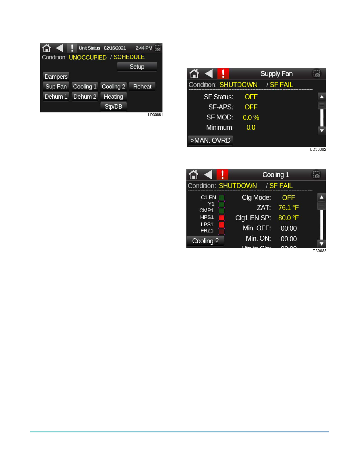
Figure 6: Unit status screen
All screens will have the top two lines which includes
a home, previous, and an alarm link. These links
on the Unit Status screen are followed by the date
and time. The next line will have the operational
condition/mode of the unit. This screen will have
links depending on the options of the unit, such
as ECW (Energy Wheel), Econ (Economizer), EF
Fan (Exhaust Fan), HP1 and HP2 (Heat Pump)
not shown, see Sequence of Operation for specific
configuration. Below are two status screens.
You can use this screens to test your Sequence
of Operation on the unit. The Supply fan status
screen shows the supply fan (SF) status is turned
On and the UO9 light will be On. The SF_APS is the
feedback from the Air Proven Switch or a current
sensor. The SF MOD is the percentage output of
the VFD. Minimum is the lowest speed the SF can
run (default is 50% or 30 Hz.). The second screen is
for Cooling 1 status. On the left side of the screen
are different status points. C1 EN will light when
the ZAT is 1°F above the Clg1 EN SP. Y1 will light
when the compressor 1 command or UO10 is turned
On. CMP1 will light when the current sensor closes
for compressor 1. HPS1 and LPS1 should always
have the light on. FRZ1 will light when the DXLAT1
sensor is below 38°F. Clg Mode will be on, when
OAT is above 55°F and there is demand for cooling
or dehumidification. Min off and on are 5 minute
timers. When the compressor starts or stops it
must remain or be off for 5 minutes. They will start
at 5 minutes and count down. These timers meet
Copelands requirement of 6 starts an hour. There
are two of the status screens for this unit. The
rest of the status screen are similar by using the
Sequence of Operation, then you can check the status
of unit.
Figure 7: Unit status screen 1
Figure 8: Unit status screen 2
Tech settings screen
The Tech Settings screen can be accessed by
selecting the Setup link from the Unit Status
screen. The Tech Settings screen includes
navigating links for Unit Config screen, Tech
Setup screen, Schedule screen, Calibration
screen, etc. Here is where you will be able to add
and/or calibrate sensors and access screens for
occupancy control and settings. Just like the Unit
Status screen, the Tech Settings screen will have
additional links such as DPT, AMS, Reset (ZAT/SAT),
based on unit configuration.
Quick Start Guide for Equipment Touch and LS-1628 Unit Controller, Standard 3.1.5 Program4

Figure 9: Tech settings screen
Note:
• A: Back to Unit status screen.
• B: Shows model and program version,
optical sensor enable options.
• C: Allows calibration of all installed sensors
for temp and humidity.
• D: Allows manual inputs of adjustable
setpoints and deadbands.
• E: Occupancy control, shut down settings,
supports.
• F: Schedule is used to setup an internal
schedule on the controller.
• G: Screen title.
Tech setup screen
Tech setup allows for unit override controls and
certain operational parameters. Parameters that
can adjust/changed in tech setup are occupancy
control, unit enable supply fan minimum run
settings, ZAT/SAT reset on/off, emergency heat
enable and many more.
Please refer to specific unit sequence of operation
for specific run conditions and set points.
Figure 10: Tech setup screen
Unit configuration screen
To access the Unit configuration screen, select
the Unit Config link on the Tech Settings screen.
The Unit configuration screen you can select
options for miscellaneous controls that are FACTORY
options. This screen also displays the factory S/
N and unit configuration, zone sensor set up
(optional), night set back options can be enabled
and miscellaneous options A and B (COS, SD, CFI).
Quick Start Guide for Equipment Touch and LS-1628 Unit Controller, Standard 3.1.5 Program 5

Figure 11: Unit configuration screen
Note:
• A: Unit configuration by factory selected
options.
• B: Factory serial number (unit serial
number).
• C: Optional, can add a zone sensor if
needed.
The following four charts show all avaibable options
for the four selectable drop-down menus. These
options can be added to the unit or may have come
from the factory.
Figure 12: ZAT sensor options
Figure 13: Option A
Figure 14: Option B
Quick Start Guide for Equipment Touch and LS-1628 Unit Controller, Standard 3.1.5 Program6

Figure 15: NSB options Calibration screen: control sensor
readouts and manual adjustments
Use the Calibration screen to see all sensor values
and to apply an offset. The value shown represents
the current value + the offset given. This screen is
used for testing purposes to enable an operational
state or to calibrate a sensor reading.
Figure 16: Calibration screen
Note: The Calibration screen displays the
current value + offset. If the offset is zero, the
value is current sensor reading.
Quick Start Guide for Equipment Touch and LS-1628 Unit Controller, Standard 3.1.5 Program 7
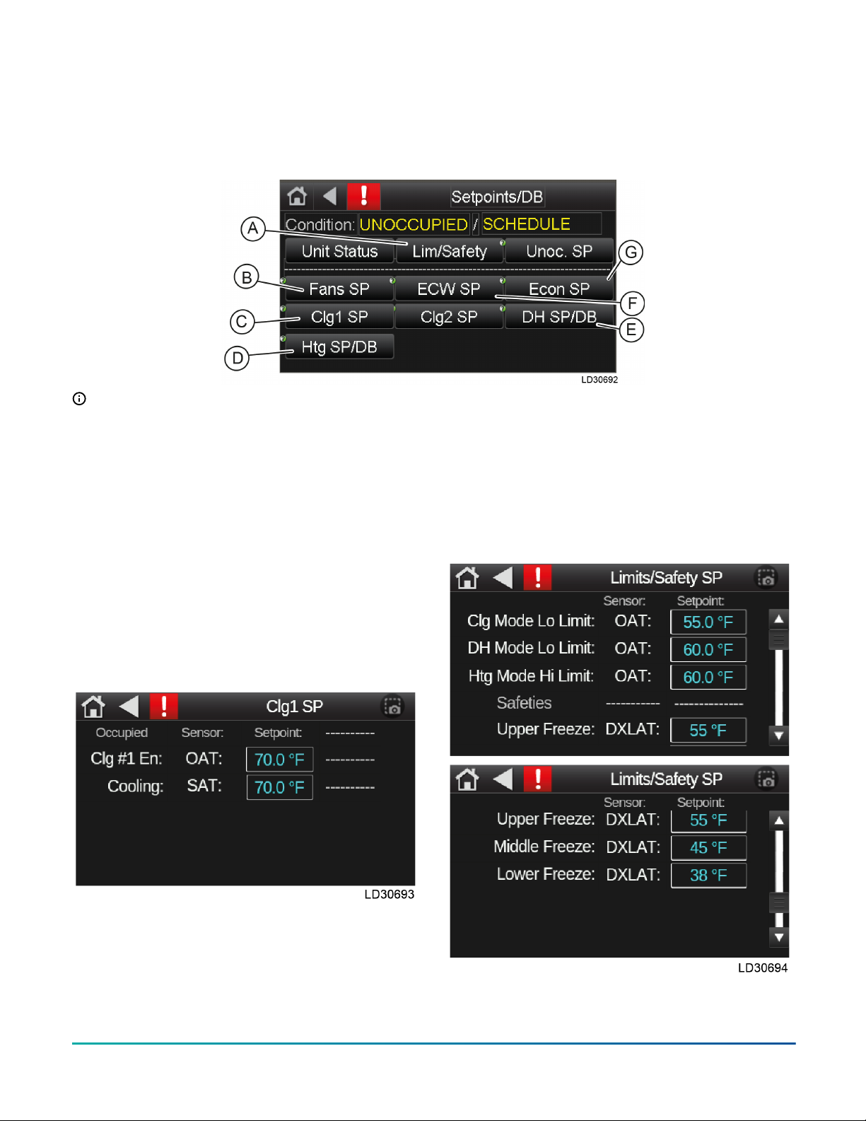
Setpoint and deadband screen
The Setpoints/DB screen allows you to adjust any
setpoints that need to be adjusted through field
test and balancing. These setpoint come preset to
a factory setting during the initial program unless
requested otherwise. Admin password is required to
access and change any setpoints.
Figure 17: Setpoint and deadband screen
Note:
• A: Limits and safeties
• B: Supply and exhaust fans setpoints and
deadbands
• C: Cooling setpoints (Clg1 SP and Clg2 SP)
• D: Heating setpoint and deadband
• E: Dehumidification setpoint and
deadband
• F: Energy wheel setpoint and deadband
• G: Economizer setpoint
See for an example of the setpoint screens available
from the Setpoints/DB screen.
Figure 18: Cooling 1 setpoint
These setpoints are all adjustable, the sensor is NOT
adjustable and is for information only.
Limits and safety setpoints
The Limits/Safety SP screen allows you to see the
lower and upper limits of the deadbands. These
deadbands are editable and the standard values are
set from the factory. An admin password is required
to access the Limits/Safety SP screen.
The sensor tag is not adjustable and for information
purposes only. The sensors are set from factory and
can only be changed or modified when instructed
to do so by technical service. If you have any
questions, please call technical service.
Figure 19: Limits and safety setpoints
Quick Start Guide for Equipment Touch and LS-1628 Unit Controller, Standard 3.1.5 Program8

Default limits: all values are degrees Fahrenheit
• Cooling mode Lo Limit: 40° to 65°
• Dehumidification mode Lo Limit: 55° to 90°
• Heating mode Upper Limit: 40° to 70°
• Compressor disable OAT: 0° to 50°
• Upper freeze protection: 28° to 55°
• Middle freeze protection: 28° to 55°
• Lower freeze protection: 28° to 55°
• ECW defrost WExAT: 0° to 20,000°
Occupancy control
Press the Occupancy Control drop down menu
option, the Occupancy Control parameter dictates
where the unit control for occupied mode of the unit
originates, all modes can be set in the field and/or
overridden by the BAS.
Figure 20: Occupancy control
•Local schedule – internal schedule on the
controller.
•BAS control – building automated system
controls unit enable by writing to manual occ
control point, occ enable.
•24/7 operation – runs continuously, unit does
not have an unoccupied mode unless the
occupancy enable is changed.
•S/S switch – on/off signal control, could be a
switch or a digital input (DI) (UI12, option A
selected in ET2)
•CO2 occupancy – CO2 sensor enabled control.
When the CO2 level reaches 300 ppm, the unit
will be placed in occupied mode.
Note: This will require a CO2 zone (space)
sensor for reading space CO2 and enabled
in Config screen on ET2.
Setting a schedule
There is no default schedule for the LOCAL SCH option. Change the schedule to the desired hours. To edit
the schedule, select the Schedule button on the Setup Status screen.
1. Click the Add Schedule button in upper right corner.
2. Enter a name for the schedule – example here is named Addison Schedule.
Quick Start Guide for Equipment Touch and LS-1628 Unit Controller, Standard 3.1.5 Program 9

3. Select schedule type – you can choose On schedule - occupied or Off schedule - Unoccupied.
4. Select time and date – we recommend weekly schedules. Leave the Date Range to NO. Make sure to set
the time to the hours for occupied schedule unless otherwise stated by customer.
5. Click Save Schedule button on bottom of screen. Then press OK button.
Quick Start Guide for Equipment Touch and LS-1628 Unit Controller, Standard 3.1.5 Program10
Tabla de contenidos


