TeeJet AEROS9040 Manual de usuario

USER GUIDE
AEROS9040
Software version 4.31

Table of Contents
START SIMPLE GUIDANCE 1
#1 POWER ON 1
#2 HOME SCREEN 1
System Setup .................................................................................................................................................................1
RealView Camera Full Screen Video View......................................................................................................................1
ISOBUS Universal Terminal View ....................................................................................................................................1
Simple or Advanced Mode.........................................................................................................................................1
#3 GO TO CONFIGURATION 2
1) Set Up the Local Cultural Settings.......................................................................................................................................................2
2) Set Up the GNSS.........................................................................................................................................................................................2
3) Set Up the Implement..............................................................................................................................................................................3
Implement Settings per Equipment Present...............................................................................................................3
Single Section Setup ......................................................................................................................................................3
Section(s) with ISOBUS Sprayer/Spreader Setup...........................................................................................................4
Additional Settings per Implement Type ....................................................................................................................4
Section Numbers .............................................................................................................................................................5
Straight ............................................................................................................................................................................5
Spreader – TeeJet............................................................................................................................................................6
Lateral Implement Offset Distance Adjustment ..........................................................................................................7
GNSS Offset Adjustment Calculation...............................................................................................................................7
Lateral Implement Offset Adjustment...............................................................................................................................8
4) Set Up the Mapping Location ...............................................................................................................................................................9
#4 START NEW JOB OR CONTINUE JOB 10
Simple Mode ................................................................................................................................................................................................. 10
Advanced Mode........................................................................................................................................................................................... 10
#5 SET UP GUIDANCE 11
1) Choose a Guidance Mode.................................................................................................................................................................... 11
2) Establish an AB guideline .................................................................................................................................................................... 12
3) Create an Application Boundary....................................................................................................................................................... 12
ADD RATE CONTROL 14
Guidance Screen Options......................................................................................................................................................................... 14
MAPPING OPTIONS 15
Duplicating and Transferring Maps ................................................................................................................................15
Coverage Map............................................................................................................................................................................................... 16
Polygons Map ............................................................................................................................................................................................... 16
Prescription Map.......................................................................................................................................................................................... 16
Application and Target Rate Maps ........................................................................................................................................................ 17
Target Rates...................................................................................................................................................................17
Color Range Selection ............................................................................................................................................17

iii
98-01504-ENUS R2
Aeros 9040 Field Computer
INFORMATION ON GUIDANCE MODES 18
Vehicle View................................................................................................................................................................................................... 18
Field View........................................................................................................................................................................................................ 18
RealView Guidance ..................................................................................................................................................................................... 19
GUIDANCE MODES 19
Straight AB Guidance................................................................................................................................................................................. 19
Curved AB Guidance .................................................................................................................................................................................. 19
Adaptive Curve AB Guidance.................................................................................................................................................................. 19
Circle Pivot Guidance ................................................................................................................................................................................. 20
Last Pass Guidance...................................................................................................................................................................................... 20
NextRow Guidance ..................................................................................................................................................................................... 20
No Guidance.................................................................................................................................................................................................. 20
SCREENS OPTIONS 21
GUIDANCE BAR 25
STATUS BAR 26
GUIDANCE FEATURES DETAILS 27
A+ Nudge Feature....................................................................................................................................................................................... 27
Azimuth Degree........................................................................................................................................................................................... 27
Return to Point.............................................................................................................................................................................................. 28
Next Guideline Feature.............................................................................................................................................................................. 29
REFRESH GNSS POSITION 29
BOOMPILOT 30
No Section Control Module ..................................................................................................................................................................... 30
ISOBUS Sprayer............................................................................................................................................................................................. 30
ISOBUS Spreader.......................................................................................................................................................................................... 31
With TeeJet Section Control Module And Switchbox or ISM....................................................................................................... 32
With TeeJet Section Control Module .................................................................................................................................................... 32
ADDITIONAL IMPLEMENT OPTIONS 33
TIP SELECTION 33
Preset .....................................................................................................................................................................33
Tip Sizes and Associated Colors....................................................................................................................................33
Current Tip..............................................................................................................................................................34
DROPLET SIZE MONITOR 34
Setup................................................................................................................................................................................................................ 34
Enable/Disable DSM ...............................................................................................................................................34
Tip Selection / Current Tip.......................................................................................................................................34
Input/Output Module Pressure Sensor.....................................................................................................................34

iv www.teejet.com
Aeros 9040 Field Computer
Operation ....................................................................................................................................................................................................... 35
Status Bar...............................................................................................................................................................35
Droplet Size Chart..........................................................................................................................................................35
Guidance Bar ..........................................................................................................................................................35
REVERSE SENSE 36
BOOMPILOT SECTION CONTROL 37
TIP FLOW MONITOR 38
ISOBUS SPRAYER OFFSETS 38
Self-propelled ............................................................................................................................................................................................... 39
Three Point Hitch ......................................................................................................................................................................................... 39
Trailed .............................................................................................................................................................................................................. 40
DATA MANAGEMENT 41
Job Data .......................................................................................................................................................................................................... 42
Copy Job Data ...............................................................................................................................................................42
Machine Settings......................................................................................................................................................................................... 43
Copy Machine Prole.....................................................................................................................................................43
SYSTEM CONFIGURATIONS 44
Safety Information
TeeJet Technologies is not responsible for damage or physical harm caused by failure to adhere to the following safety requirements.
As the operator of the vehicle, you are responsible for its safe operation.
The Aeros 9040 in combination with any assisted/auto steering device is not designed to replace the vehicle’s operator.
Do not leave a vehicle while the Aeros 9040 is engaged.
Be sure that the area around the vehicle is clear of people and obstacles before and during engagement.
The Aeros 9040 is designed to support and improve efciency while working in the eld. The driver has full responsibility for the quality and work
related results.
Disengage or remove any assisted/auto steering device before operating on public roads.

1
98-01504-ENUS R2
Aeros 9040 Field Computer
START SIMPLE GUIDANCE
#1 POWER ON
Integrated RAM Mount
(assembly required)
Speed Digital (LAN)
Connection
with Rubber Cover
Camera Connection
with Rubber Cover
Power Connection
Speakers
GNSS Antenna Connection
WiFi Antenna Connection
USB Ports with Rubber
Covers
USB Ports with Rubber Covers
Bright Touch Screen
Power Button
Favorites Button
Home Button
Recommended Antenna Installation
The GNSS antenna should be mounted as far forward as possible on
top of the cab on a metal surface of at least 4 in × 4 in / 10 cm × 10 cm.
Home Button
The Home button provides a shortcut to the Home screen.
Power On/Off Button
On – Press the POWER button to power on the console. Upon
power up, the Aeros will begin its start up sequence.
Off – Press and briey hold the POWER button until a conrmation
screen acknowledges shut down mode.
WARNING! Wait 10 seconds before restarting the console.
#2 HOME SCREEN
Once the power up sequence has completed, the Home screen will
appear with the options to start a new job or continue an existing job.
Home/Job Screen (or press Home Button)
Unit Setup
RealView Camera Full Screen Video View
ISOBUS Universal Terminal
System Setup
System Setup is used to congure the console, the machine and its
implements. Four side tabs access options for Machine/Implement
Conguration, Data Management, Console Settings, and Tools.
RealView Camera Full Screen Video View
View video feed(s) and setup cameras without GNSS available.
Options for RealView Guidance are not available on this screen.
ISOBUS Universal Terminal View
Access to an ISOBUS Electronic Control Unit (ECU) options and
operation. This provides crop sprayer or spreader control when
integrated into the implement of either capability.
Simple or Advanced Mode
To change between simple mode and advanced mode, see the
conguration chapter under Data –> Options.
►Simple Mode – only one job will be available at a time. Only
bounded area and coverage areas are displayed on the home
screen. Only the current job is available for saving in Reports.
Use with Fieldware Link is not available.
►Advanced Mode – more than one job will be available at any
time. Client, farm, eld and job names; bounded and coverage
areas; application time; and distance from selected job are
displayed on the home screen. All saved job proles can be
exported as a PDF, SHP or KML le to a USB drive using
Data -> Reports.

2www.teejet.com
Aeros 9040 Field Computer
#3 GO TO CONFIGURATION
From the Home screen, select the System Setup bottom button to congure the console, the machine and its implements. Four side tabs access
options for Machine/Implement Conguration, Data Management, Console Settings, and Tools.
Conguration side tab
Data Management side tab
Console Settings side tab
Tools side tab
System Setup bottom tab
Side Tabs
1) Set Up the Local Cultural Settings
Cultural is used to congure units, language, and time zone settings
for the Aeros console and any Electronic Control Units (ECUs) in the
system.
NOTE: The languages available in a particular ECU may vary.
1. Press SYSTEM SETUP bottom tab .
2. Press CONSOLE side tab .
3. Press Cultural .
4. Select from:
►Units – used to dene the system units
►Language – used to dene the system language
►Time Zone – used to establish the local time zone
2) Set Up the GNSS
GGNSS Receiver Conguration is used to congure GNSS Type,
GNSS Port, and PRN, and other GNSS parameters, and to view GNSS
status information.
1. Press SYSTEM SETUP bottom tab .
2. Press CONFIGURATION side tab .
3. Press GNSS Receiver Conguration .
4. Select from:
►GNSS Type – sets to accept GNSS source transmissions: GPS,
GLONASS, SBAS (with or without DGPS Required)
►GNSS Port – sets GNSS communication port to either Internal
or External
►GNSS Status Information – displays current GNSS status
information
►Program – only TeeJet support technicians should use this
feature
►PRN – selects the rst of two possible SBAS PRN’s to provide
SBAS correction data. Set to Automatic for automatic PRN
selection.
►Alternate PRN – when PRN is not automatic, allows possible
selection of a second SBAS PRN to provide correction data
►Show refresh GNSS position button – establishes if the refresh
GNSS position button is available on the guidance screens.
5. Press NEXT PAGE arrow to set up the selected specic GNSS
options.
6. Select:
►GPS – single point uncorrected position data based on GPS only
with a GGA QI of “1” is accepted.
NOTE: GPS is always selected.
►GPS+GLONASS – single point uncorrected position data based
on GPS and GLONASS with a GGA QI of “1” is accepted.

3
98-01504-ENUS R2
Aeros 9040 Field Computer
►GPS+SBAS – either single point uncorrected or SBAS corrected
position data are accepted - GGA QI of “1” or “2” (3, 4 or 5 are
also accepted).
►GPS+GLONASS+SBAS – either single point uncorrected or
SBAS corrected position data are accepted - GGA QI of “1” or
“2” (3, 4 or 5 are also accepted).
►GPS+GLONASS+SBAS+DGPS – only GGA data with a QI value
of “2” or higher is accepted (3, 4 or 5 are also accepted).
NOTE: All console based mapping, application and guidance
functions are ceased if the GGA QI value drops below “2” with
this setting checked.
7. Exit this screen to begin initializing the GNSS receiver. This takes
about a minute, and the console will not respond until complete.
3) Set Up the Implement
Implement Setup is used to establish the various settings associated
with straight mode, spreader mode, or staggered mode. Available
settings will vary depending on the specic equipment present in the
system.
Implement Settings per Equipment Present
This section includes setup options for these implement congurations:
►Single Section
►Section(s) with ISOBUS Sprayer/Spreader Setup
Single Section Setup
Single Section Setup is used when a SmartCable, Section Driver
Module (SDM), or Switch Function Module (SFM) is not on the system
(that is, no section control is present). The entire boom or delivery area
is considered to be one section.
1. Press CONFIGURATION side tab .
2. Press Implement .
3. Select from:
►Machine Type [when available]– used to select the type of
machine that most closely represents your machine
►GNSS Antenna Height [when available]– used to measure the
height of the antenna from the ground
►Implement Type – used to select the layout of the sections for
the applied product location (see Implement Type section for
additional details)
►Working/ Application Width – used to enter the total width of the
implement. Range is 3.28 to 246.06 feet / 1.0 to 75.0 meters.
►Droplet Size Monitor [when available] – used to enable droplet
size monitoring for up to ve preselected sprayer tips
►Tip Selection [when available] – used to select the type of
sprayer tip (series and capacity) for determining droplet size
information
►Applied Alert – used to establish an alert to signal when exiting
or entering an applied area
►BoomPilot Start Mode – used to establish whether BoomPilot will
be controlled by speed or by the BoomPilot icon

4www.teejet.com
Aeros 9040 Field Computer
►BoomPilot Icon – used to activate the guidance screen icon for
manually controlling on-screen application painting
4. Press NEXT PAGE arrow to set up specic implement options.
See the Implement chapter for details.
Section(s) with ISOBUS Sprayer/Spreader Setup
Some Implement options are completed on the ISOBUS ECU. When
these options are also available in the Implement Setup section, they
will be grayed out or unavailable.
1. Press CONFIGURATION side tab .
2. Press Implement .
3. Select from:
►Machine Type [when available] – used to select the type of
machine that most closely represents your machine
►GNSS Antenna Height [when available] – used to measure the
height of the antenna from the ground
►Implement Type – used to select the layout of the sections for
the applied product location
►Application Width [Straight Implement Type completed on
ISOBUS ECU] – used to display the total width of the implement
as entered on the ISOBUS sprayer
►Working Width [Spreader Implement Type completed on the
ISOBUS ECU] – used to display the total width of the implement
as entered on the ISOBUS spreader
►Droplet Size Monitor [available only with Pressure Sensor
Interface Kit] – used to enable droplet size monitoring for up to
ve sprayer tips
►Tip Selection [Straight Implement Type completed on the
ISOBUS ECU] – used to display the type of sprayer tip as
entered on the ISOBUS sprayer
►Applied Alert – [only available without a switchbox] used to
establish an alert to signal when exiting or entering an applied
area
►BoomPilot Start Mode – used to control BoomPilot automatically
by speed, or manually by BoomPilot icon
►BoomPilot Icon – used to activate icon for manually controlling
BoomPilot
4. Press NEXT PAGE arrow to set up specic implement options.
Additional Settings per Implement Type
Implement Type selects the type of application pattern that most closely
represents your system.
● In Straight Mode – the boom sections have no length and are on
a line a xed distance from the antenna
● In Spreader Mode – a virtual line is created in line with the delivery
disks from which the application section or sections can vary in
length and can be at different distances from the line (availability
depends on the specic equipment in the system)
● In Staggered Mode – a virtual line is created in line with
Section 1 from which the application section or sections have no
length and can be at different distances from the line (availability
depends on the specic equipment in the system)
Figure 1: Implement Type – Straight
54321

5
98-01504-ENUS R2
Aeros 9040 Field Computer
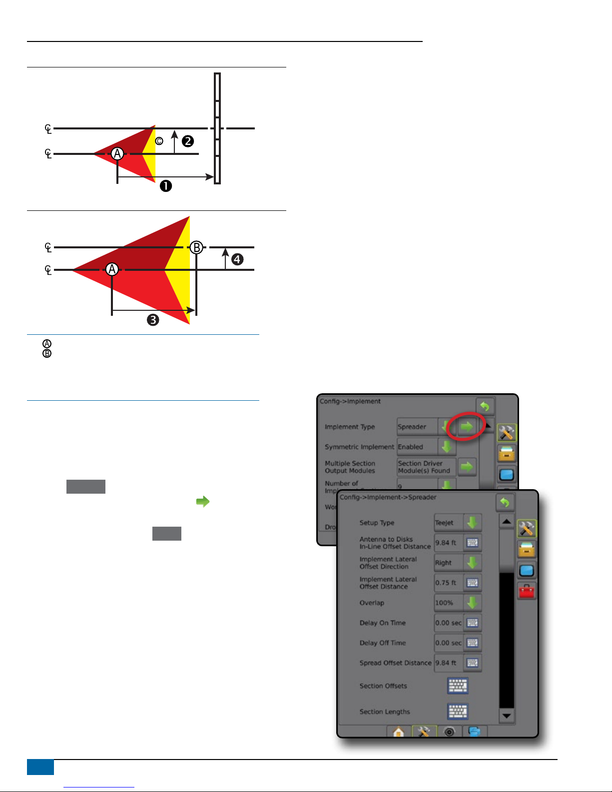
Figure 2: Implement Type – Spreader
5
6
7
43
2
1
Figure 3: Implement Type – Staggered
5
432
1
Section Numbers
Sections are numbered from left to right while facing in the machine’s
forward direction.
Straight
The boom sections have no length and are on a line a xed distance
from the antenna.
1. Select Straight implement type on Implement screen.
2. Press Implement Type NEXT PAGE arrow .
3. Select from:
►Connection Point In-line Offset Direction [ISOBUS only] –
establishes if reference point is located in front of (forward)
or behind (backward) the GNSS antenna while facing in the
machine’s forward direction
►Connection Point In-line Offset Distance [ISOBUS only]–
measured in parallel to the centerline of the machine, denes the
in-line distance from the GNSS antenna to reference point
►Connection Point Lateral Offset Direction [ISOBUS
only]– denes the lateral direction, either left or right, from the
centerline of the machine to the center of reference point
while facing in the machine’s forward direction
►Connection Point Lateral Offset Distance [ISOBUS only]–
denes the lateral distance from the centerline of the machine to
the center of reference point
►Implement In-line Offset Direction – displays if the implement
is located in front of (forward) or behind (backward) the GNSS
antenna while facing in the machine’s forward direction
►Implement In-line Offset Distance – measured in parallel to
the centerline of the machine, displays the in-line distance from
the GNSS antenna to the implement
►Implement Lateral Offset Direction – displays the lateral
direction, either left or right, from the centerline of the machine
to the center of the implement while facing in the machine’s
forward direction
►Implement Lateral Offset Distance – displays the lateral
distance from the centerline of the machine to the center of the
implement
►Overlap – used to dene the amount of overlap allowed when
using automatic boom section control
►Delay On Time – used to set the time when the section will
switch on when entering an area that has not been applied
NOTE: If the application turns on too soon when entering an
unapplied area, decrease the Delay On Time. If the application
turns on too late, increase the Delay On Time.
►Delay Off Time – used to set the time when the section will
switch off when entering an area that has been applied
NOTE: If the application turns off too soon when entering an
unapplied area, decrease the Delay Off Time. If the application
turns off too late, increase the Delay Off Time.
*Available with SmartCable, Section Driver Module (SDM) or Switch
Function Module (SFM) or ISOBUS)

6www.teejet.com
Aeros 9040 Field Computer
Figure 4: Implement Offset Directions and Distances
Figure 5: Connection Point Offset Directions and Distances
– Center of the GNSS antenna
– Reference point
– Implement In-line Offset Direction/Distance
– Implement Lateral Offset Direction/Distance
– Connection Point In-line Offset Direction/Distance
– Connection Point Lateral Offset Direction/Distance
Spreader – TeeJet
A virtual line is created in line with the delivery disks from which the
application section or sections can vary in length and can be at different
distances from the line (availability depends on the specic equipment
in the system).
1. Select Spreader implement type on Implement screen.
2. Press Implement Type NEXT PAGE arrow .
3. Select from:
►Setup type – used to select TeeJet spreader type
►Antenna to Disks In-line Offset Distance – measured in
parallel to the centerline of the machine, denes the in-line
distance from the GNSS antenna to the disks, or dispersal
mechanism
►Implement Lateral Offset Direction – denes the lateral
direction, either left or right, from the centerline of the machine
to the center of the implement while facing in the machine’s
forward direction
►Implement Lateral Offset Distance – denes the lateral
distance from the centerline of the machine to the center of the
implement
►Overlap – used to dene the amount of overlap allowed when
using automatic boom section control
►Delay On Time – used to set the time when the section will
switch on when entering an area that has not been applied
NOTE: If the application turns on too soon when entering an
unapplied area, decrease the Delay On Time. If the application
turns on too late, increase the Delay On Time.
►Delay Off Time – used to set the time when the section will
switch off when entering an area that has been applied
NOTE: If the application turns off too soon when entering an
unapplied area, decrease the Delay Off Time. If the application
turns off too late, increase the Delay Off Time.
►Spread Offset Distance – used to set the distance between
the disks or dispersal mechanism and where product initially hits
the ground on Section 1.
►Section Offsets – used to set the offset distance from
section 1 (the Spread offset line) to the leading edge of each
section. Section 1 is always 0. All other sections can be different
distances.
►Section Lengths – used to set the length of application in
each section. Each section can be a different length.
NOTE: Sections are numbered from left to right while facing in
the machine’s forward direction.
*Available with SmartCable, Section Driver Module (SDM), or Switch
Function Module (SFM) or ISOBUS)
Tabla de contenidos


