10
Appendix B
Switching-on the receiver
1. Switching-on the receiver
When the receiver is switched on, the display shows the following sequence: manufacturer’s
trademark (logo) «TECHNO-AC», Business card of the Receiver with the Software version number
and the Start window (fig.А.1).
When switching the receiver with the button while
holding button , after Business card Window of network
frequency selection will appear. Frequency of 50 Hz or
60 Hz is selected by any of button ◄/►, and «input» with
transfer to Start window is performed by pressing the button again
.
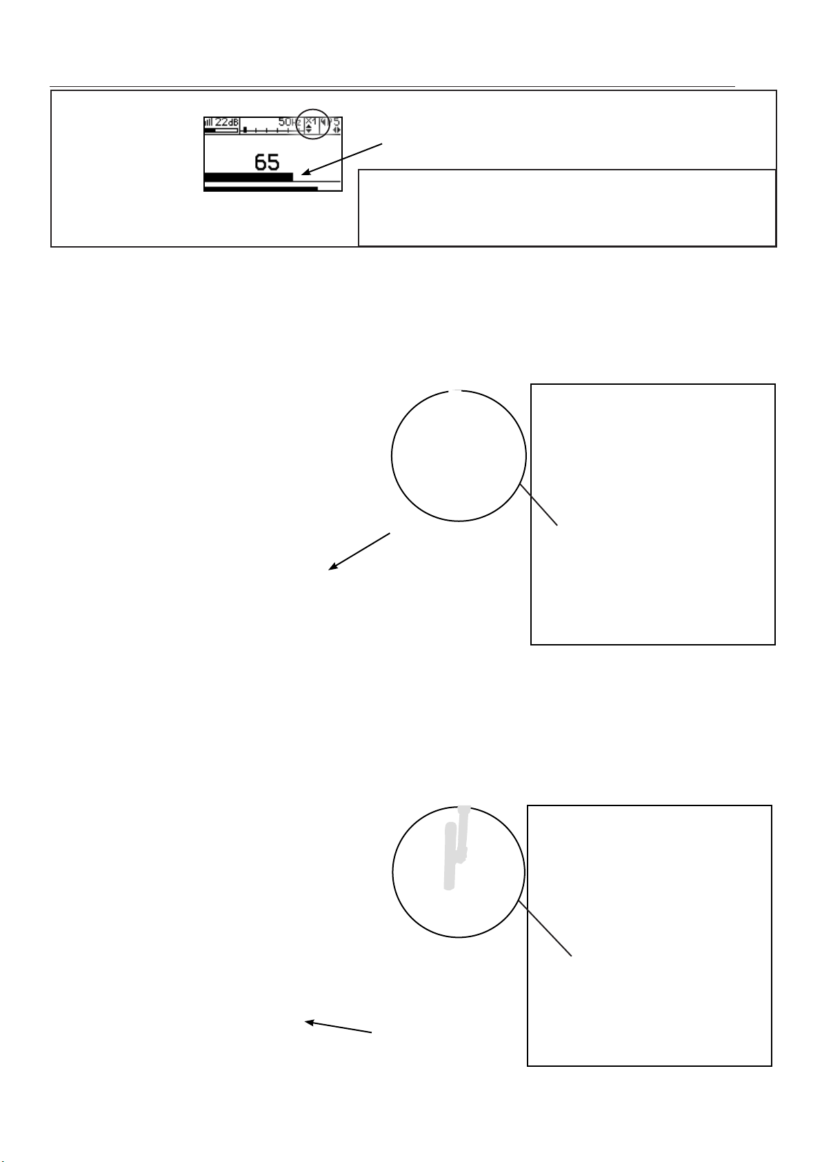
2. The start window
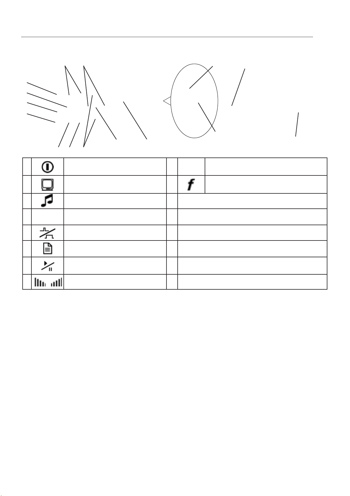
The start window displays the following information:
Fig.А.1
voltage indicator
When power voltage ≤4.0V after
switching on the warning signal
is heard, when power voltage ≤
3.8V there is the image of fully
discharged battery and the
device will automatically
switch off after
type of the sensor
connected
Sensor not connected
Acoustic sensor(AD)
Electromagnetic sensor(EMD)
type of signal received
when working with AD
- «sound of liquid leakage (continuous acoustic signal)
- «sound generated by an impact (acoustic impulses during transmitter
operation)
During work with electromagnetic sensor
-continuous signal from the power network, cathode protection of
trace generator
- pulsed signal of trace generator
- Dual-frequency signal of the trace generator
indicator backlighting intensity
There are four levels of indicator
backlighting intensity
/ / /
Fig. А.2
parameters of detector of
harmonic component with net
frequency
№ and frequency of harmonic
component of net frequency (for the
second filter)
indicators of used buttons
Type of signal received, available
for this of the sensor is selected
by ▲/▼ buttons
№ of harmonic component of
the net frequency (for the second
filter) is selected by buttons
/
Indicator backlighting intensity is
selected by the buttons◄/►
Return to the Start Window from measurement mode is performed by pressing ((pause
mode) and .