tau PIVOT Manual de usuario
GUIDA ALL’INSTALLAZIONE - INSTALLATION GUIDE INSTALLATIONSANLEITUNG - NOTICE D’INSTALLATION - GUÍA PARA LA
INSTALACIÓN
ALLINEAMENTO - ALIGNMENT - AUSRICHTUNG - ALIGNEMENT - ALINEACIÓN:
RISPETTARE ALTEZZE E DIREZIONE. Ad allineamento avvenuto il led sul ricevitore si spegnerà - OBSERVE HEIGHTS AND DIRECTION. After alignment,
the LED on the receiver will put out - HÖHEN UND RICHTUNG BEACHTEN. Nach erfolgter bündigen Einbau, wird die LED am Empfänger ausschalten
- RESPECTER LES HAUTEURS ET LA DIRECTION. Quand l’alignement est eectué, la LED sur le récepteur s’eteindre - RESPETE LAS ALTURAS y
DIRECCIÓN. Una vez hecha la alineación, se apagarà el indicador luminoso en el receptor.
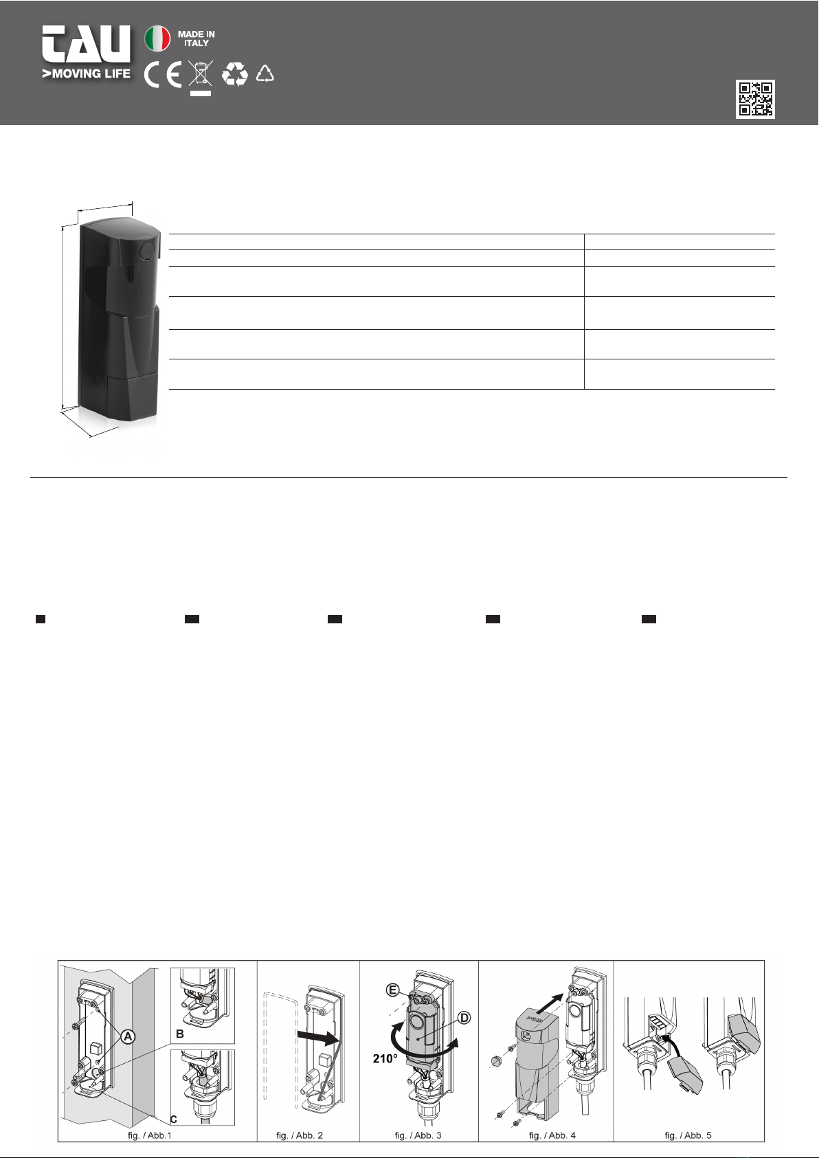
MONTAGGIO - FITTING - MONTAGE - MONTAGE - MONTAJE
IT EN DE FR ES
1Fissare la base della fotocellule
alla colonna o muro usando
i fori presenti (A g.1). Far
passare i cavi tramite i fori
(Be C g. 1) con passacavo
PG9) e collegare i cavi alla
morsettiera.
2Posizionare la guarnizione in
dotazione come indicato in
gura 2.
3 Pressare all’interno della
base il gruppo lente (D g.3)
con le apposite viti (E fig.3).
Regolare l’orientamento, ad
allineamento avvenuto il Led
sul ricevitore si spegnerà.
Fissare definitivamente la
lente alla base della fotocellula
(E fig.3).
4Chiudere con il coperchio
della fotocellula e ssare le viti
(g. 4).
5Chiudere il coperchio inferiore
come in gura (g. 5) e
avvertire il “click” di chiusura.
1Fix the base of the photocells
to the column or wall using
the drilled holes (A g.1).
Pass the cables through the
holes (B and C g.1) with
fairlead PG9) and connect
the cables to the terminal
board.
2Position the supplied gasket
as shown in picture 2.
3 Pre-x the lens group on
the inside of the base using
the screws supplied (E g.3).
Adjust the orientation, when
alignment is reached the LED
on the receiver will go o. Fix
the lens onto the base of the
photocell denitely (E g.3).
4Close with the photocell
cover and x the screws
(g.4).
5Close the lower cover as
shown in the gure (g.5)
and listen for the closing
“click”.
1DieBasisderLichtschrankenandie
Säule oder an die Wand mithilfe
der vorliegenden Bohrungen
befestigen (A Abb. 1). Die Kabel
über die Bohrungen (B und C Abb.
1) mit einem Kabelniederhalter
PG9) verlegen und die Kabel an
das Klemmenbrett anschließen.
2Positionieren Sie die mitgelieferte
Dichtung wie in Abbildung 2
gezeigt.
3 Die Linsengruppe (D Abb. 3) mit
den vorgesehenen Schrauben
(E Abb. 3) in die Basis im
ersten Schritt befestigen. Die
Ausrichtung regulieren – nach
erfolgter Anpassung schaltet
sich die Led am Empfänger aus.
Die Linse denitiv an der Basis
der Lichtschranke (E Abb. 3)
befestigen.
4Mit dem Deckel der Lichtschranke
schließen und die Schrauben
befestigen (Abb. 4).
5Den unteren Deckel wie in
der Abbildung (Abb. 5) gezeigt
schließen und das abschließende
“Klick” abwarten.
1Fixer la base de la cellule
photoélectrique à la colonne
ou au mur en utilisant les trous
présents (A g.1). Faire passer les
câbles au travers des trous (B et C
g. 1) avec le serre-câble PG9) et
connecter les câbles au bornier.
2Placer la garniture fournie
comme indiqué à la gure 2.
3 Préxer à l’intérieur de la
base le groupe verre (D g.3)
avec les vis spéciales (E g.3).
Régler l’orientation, et lorsque
l’alignement est terminé le Led
sur le récepteur s’éteindra. Fixer
dénitivement le verre à la base
de la cellule photoélectrique (E
g.3).
4Fermer le couvercle de la cellule
photoélectrique et xer les vis
(g. 4).
5 Fermer le couvercle inférieur
comme sur la gure (g. 5) jusqu’à
entendre le ‘clic’ de fermeture.
1 Fijar la base de la fotocélula en la
columna o en la pared usando
los agujeros presentes (A Fig.
1). Hacer pasar los cables por
los agujeros (B y C Fig. 1) con
sujetacable PG9) y conectar los
cables a la regleta.
2 Coloque la guarnicion en
dotacion como indicado en la
gura 2
3 Prejar en el interior de la
base el grupo de lente (D Fig.
3) con los relativos tornillos (E
Fig. 3). Regular la orientación,
una vez realizada la alineación
se apagará el indicador
luminoso en el receptor. Fijar
denitivamente la lente a la
base de la fotocélula (E Fig. 3).
4Cerrar con la tapa de la
fotocélula y jar los tornillos
(Fig. 4).
5Cerrar la tapa inferior como
muestra la gura (Fig. 5) y oír el
«clic» de cierre.
CARATTERSTICHE TECNICHE - SPECIFICATIONS - TECHNISCHE EINGESHAFFEN - CARACTERISTIQUES TECHNIQUES -
CARACTERISTICAS TECNICAS
Alimentazione / Power supply / Spannung / Alimentation / Alimentaciòn 12/24 Vdc-Vac
Portata* / Range* / Senoleberelch* / Portèe* / Alcance* 20 mt
Consumo trasmettitore / Power consumption transmitter / Verbauch
Sender / Consommation emetteur / Consumo transmisor
40 (12 Vdc) mA - 60 (24 Vdc) mA
11 (12 Vac) mA - 10 (24 Vac) mA
Consumo ricevitore / Power consumption receptor / Verbauch Empfanger /
Consommation recepteur / Consumo receptor
10 (12 Vdc) mA - 11 (24 Vdc) mA
7 (12 Vac) mA - 6 (24 Vac) mA
Contatto relay in uscita / Output relay contact / Relais-Kontakt am Ausgang / Contact
relais à la sortie / Contacto relé en salida N.C. 500 mA / 24 V
Grado di protezione / Protection level / Schutzart / Degré de protection
/ Grado de protección IP 54
* In caso di particolari condizioni atmosferiche (nebbia, pioggia, neve, etc.) la portata si può ridurre del 60%. *
In case of particular atmospheric conditions (fog, rain, snow, etc.) the range can be reduced of 60%. *
Bei besonderen Wetterverhältnissen (Nebel, Regen, Schnee, etc.) kann die Reichweite bis 60% riduzieren.
*
En cas de conditions atmosphérique particulieres (brouillard, pluie, nerge, etc.) la portée peut se reduire du
60%.
*
En caso de condiciones atmósfericas particulares (niebla, lluvia, nieve, etc.) l’alcance se puede reducir
del 60%.
38
121
43
900PIVOT
PIVOT
TAU srl - Via Enrico Fermi, 43 - 36066 Sandrigo (VI) - Italy
Tel +39 0444 750190 - Fax +39 0444 750376
www.tauitalia.com
D-MNL0PIVOT
30-11-22 - Rev.02
Foglietto illustrativo - CARTA - Raccolta dierenziata
Segui le indicazioni del tuo comune.
Instruction leaet - PAPER - Waste separation
Follow the instructions of your city hall
22
PAP
Fotodispositivo
infrarosso
regolabile 210°
Adjustable
infrared
photocell 210°
Photocellule
avec rotation
210°
Infrarot
Lichtschranke
schwenkbar bis 210°
Fotodispositivo
infrarrojo
ajustable 210º

COLLEGAMENTI - CONNECTIONS - ANSCHLÜSSE RACCORDEMENTS - CONEXIONES
DICHIARAZIONE CE DI CONFORMITÀ / EC DECLARATION OF CONFIRMITY / EG-KONFORMITATSERKLARUNG
DÉCLARATION CE DE CONFORMITÉ / DECLARACION CE DE CONFORMIDAD
Con la presente dichiariamo che il nostro prodotto / We hereby declare that our product / Hiermit erklaren wir, dass unser Produkt Nous déclarons par la présente que notre produit / Por la
presente declaramos que nuestro producto: 900PIVOT
è conforme alle seguenti disposizioni pertinenti: / complies with the following relevant provisions: / folgenden einschlagigen Bestimmungen entspricht: correspond aux dispositions
pertinentes suivantes: / satisface las disposiciones pertinentes siguientes: 2006/42/CE, 2014/35/EU, 2014/30/EU (EN 61000-6-2; EN 61000-6-3)
Il Rappresentante Legale / The legal Representative / Der gesetzliche Vertreter / Le
Représentant Légal / El Representante Legal
_________________________________________
Loris Virgilio Danieli
TX RX
SISTEMA DI SINCRONISMO - SYNCHRONISM SYSTEM - GLEICHLAUFSYSTEM - SYSTÈME
DE SYNCHRONISME - SISTEMA DE SINCRONÍA
IT Se avete la necessità di installare più di una fotocellula molto vicine tra loro è necessario
collegarle tutte insieme come indicato nello schema a anco e codicare i ponticelli (J3,J4,J5)
dei dispositivi come in tabella. 0→ ; 1→ ; es. 0 0 1 →
EN If you need to install more than a photocell near to each other, they need to be
connected all together as shown in the diagram on the side and the jumpers (J3, J4, J5) of
the devices must be codied as in the table.
0→ ; 1→ ; es. 0 0 1→
DE Wenn Sie mehrere Lichtschranken eng nacheinander installieren wollen, müssen sie alle
- wie im nebenstehenden Schema aufgeführt - angeschlossen und die Brücken (J3, J4, J5) der
Vorrichtungen laut Tabelle codiert werden.
0→ ; 1→ ; es. 0 0 1 →
FR Si vous devez installer plusieurs cellules photoélectriques très proches les unes des
autres, il est nécessaire de les connecter ensemble comme indiqué sur le schéma ci-contre
et de coder les cavaliers (J3, J4, J5) des dispositifs comme indiqué dans le tableau.
0→ ; 1→ ; es. 0 0 1 →
ES Si necesitan instalar varias fotocélulas muy cercanas entre ellas es necesario conectarlas
todas juntas como se indica en el esquema de al lado y codicar los puentes (J3, J4, J5) de
los dispositivos como se muestra en la tabla.
0→ ; 1→ ; es. 0 0 1 →
J5 J4 J3 Descrizione - Description - Beschreibung - Description - Descripción
0 0 0 Sincronismo disabilitato - Synchronisation disabled - Synchronismus
deaktiviert - Synchronisation désactivée - Sincronismo inhabilitado /
desactivado - Sincronismo desactivado
0 0 1 Master abilitato, canale 1 - Enabled master, channel 1 - Befähigtes Mas-
ter, Kanal 1 - Master autorisé, canal 1 - Master habilitado, canal 1
0 1 1 Slave abilitato, canale 2 - Enabled slave, channel 2 - Befähigtes Slave,
Kanal 2 - Slave autorisé, canal 2 - Slave habilitado, canal 2
1 0 1 Slave abilitato, canale 3 - Enabled slave, channel 3 - Befähigtes Slave,
Kanal 3 - Slave autorisé, canal 3 - Slave habilitado, canal 3
1 1 1 Slave abilitato, canale 4 - Enabled slave, channel 4 - Befähigtes Slave,
Kanal 4 - Slave autorisé, canal 4 - Slave habilitado, canal 4
CENTRALE DI COMANDO
CONTROL UNIT
–o 0 Vac/dc
+12÷24 Vac/dc
Com Input
Photocell input
+ 12÷24 Vac/dc
- 0 Vac/dc
PHOTO TX PHOTO RX
PHOTO RX
PHOTO RX
PHOTO RX
1
2
3
4
5
Relay Com
Relay Nc
1
2
3
4
Synchronism
J3
J4
J5
PHOTO TX
1
2
3
4
Synchronism
PHOTO TX
1
2
3
4
Synchronism
PHOTO TX
1
2
3
4
Synchronism
1
2
3
4
5
Relay Com
Relay Nc
1
2
3
4
5
Relay Com
Relay Nc
1
2
3
4
5
Relay Com
Relay Nc
J3
J4
J5
J3
J4
J5
J3
J4
J5
J3
J4
J5
J3
J4
J5
J3
J4
J5
J3
J4
J5
+ 12÷24 Vac/dc
- 0 Vac/dc
+ 12÷24 Vac/dc
- 0 Vac/dc
+ 12÷24 Vac/dc
-0 Vac/dc
+ 12÷24 Vac/dc
-0 Vac/dc
+ 12÷24 Vac/dc
-0 Vac/dc
+ 12÷24 Vac/dc
- 0 Vac/dc
+ 12÷24 Vac/dc
- 0 Vac/dc
Sandrigo, 16/04/2018
Synchronism
+12Vcc/ 24Vac
-12Vcc/ 24Vac
Courtesy light
J5 J3
J4
1 2 3 4
Common relay
NC relay
+12 ÷ 24 Vac/Vdc
1 2 3 4 5
-12 ÷ 24 Vac/Vdc
NC NA
IT Per eseguire un contatto NC (Normalmente chiuso):
- Collegare morsetti 4-5 del RX. (Fig. 1)
Per eseguire un contatto NA (Normalmente aperto):
- Spezzare l’angolino della scheda RX, in corrispondenza dei 3 fori (come
evidenziato in gura 2A) e fare una stagnatura nei due contatti eviden-
ziati. (Fig.2)
EN To make a NC (Normally Closed) contact:
- Connect terminals 4-5 of the RX. (Fig.1)
To make a NO (Normally Open) contact:
- Break o the corner of the RX card, in correspondence with the 3 holes (as
shown in gure 2A) and do the tinning of the two contacts indicated. (Fig.2)
DE Um ein Ausschaltglied einzurichten (Öner)
- Klemmen 4-5 der RX anschließen (Abb. 1)
Um ein Einschaltglied einzurichten (Schließer)
- Die Ecke der Platine RX an den 3 Önungen abbrechen (wie in Abbildung 2A
dargestellt) und die beiden hervorgehobenen Kontakte verzinnen. (Abb. 2)
Fig. 1
FRONTE / FRONT RETRO / BACK
RX RX
Fig. 2
Fig. 2A
FR Pour établir un contact NF (normalement fermé):
- Connecter les bornes 4-5 du RX. (Fig. 1)
Pour établir un contact NO (normalement ouvert):
- Casser le coin de la carte RX, en correspondance avec les 3 trous (comme indiqué sur la gure 2A) et étamer les deux contacts indiqués. (Fig.2)
ES Para realizar un contacto NC (Normalmente cerrado):
- Conectar bornes 4-5 del RX. (Fig. 1)
Para realizar un contacto NA (Normalmente abierto):
- Separar un trozo de la tarjeta RX, cerca de los 3 agujeros (como se muestra en la gura 2A) y hacer un estañado en los dos contactos destacados (Fig.2)
Este manual sirve para los siguientes modelos
1
Otros manuales de Escáner de tau


