
Tarlan Technical Little Cracker Manual de usuario

Page 1 of 18 Rev D May 2016
The “Little Cracker”
Installation Guide
Manufactured by Tarlan Technical Ltd
Salt Water Creek –New Zealand
Phone 03 3136271 Fax 03 3132814
www.littlecracker.co.nz

Page 2 of 18 Rev D May 2016
Thank you for purchasing a “Little cracker” Fire.
We are sure this fire will give you years of warmth from its professional
design and construction and of course it carries a 3 year warrantee.
For any assistance in fitting of this unit we are only a phone call away.
We offer a complete install service should you require this.
If you should find any of these instructions incorrect or confusing
please tell us!
Your fire is heavy (45kg) and precautions must be taken to ensure it
is securely anchored to your floor(if in a motor home or caravan) to
reduce the risk of it tearing free in an accident.
We strongly recommend that bolts are run right through the floor with a large plate or steel
straps placed on the underside to stop bolts from pulling through the floor.
Page 3 of 18 Rev D May 2016
Recommended Clearances
For safe operation the following clearances must be used when installing this fire.
Due to the installation being carried out by a variety of tradesmen and or owners is it imperative the operator
check for hot spots when the fire is operating, any spot hotter than 65 deg C must be protected by heat
shield.
When operating the fire if any surface that is combustible i.e. wood, lining or furniture gets to the
temperature where it is hot to touch with the back of your hand then you should be looking at
improving the heat reflectors for greater margin of safety.
This can be by installing heat deflectors or increasing the clearance to the fire.
Custom heat deflectors can be made on request by contacting Tarlan Technical Ltd. Or any sheet metal
company.
Minimum Recommended clearances:
Rear of Fire:
Combustible Surface:
From Fire to a combustible surface –i.e. wood or polystyrene insulated wall without any heat deflectors –
From Rear Heat shield : wood to be 360mm –polystyrene insulated panel 400mm.
From Sides: 310mm
Any panel temperature must not exceed 65 °C
If an additional metal sheet is placed on the wall, use spacers to hold off the wall 25mm, at the bottom of
sheet the gap from sheet to floor must be at least a 25mm as well as the top gap must be open, and then
recommended clearance can be reduced to 100mm –see attached 0404 test report and table 3.1
Sides of Fire:
Clearance from stainless heat shield to any combustible surface is 250 mm; if walls have non-combustible or
have sheet metal heat shield fitted then gap can be reduced to 100mm, closer clearances are possible but
please consult us.
Pedestal or base of fire:
150mm Pedestal: - A non combustible sheet such as cement board 6mm thick must be placed between the
mounting base and the floor.
75mm Pedestal: A non combustible 6mm sheet under mounting plate and tiles must be placed to extend
100mm past each side of the fire (do not tile under the pedestal or they will crack when bolts are drawn up)
Page 4 of 18 Rev D May 2016
Installation Instructions –Motorhome or Boat –Cabin
We recommend installing your fire on the driver’s side of your vehicle to reduce the risk of the chimney
cowl fouling overhanging trees etc. Tarlan can manufacture cowl protectors on request which is a frame that
is affixed to the roof of the bus and allows any branches etc to ride up and over the flue cap.
However fit where you want it!
For dwellings a plumber is the best man to install but we can supply the flue kit if given drawing of roof
detail.
Dwelling Flue must comply with AS NZS 2918:2000
Our Motor Home installation method is:
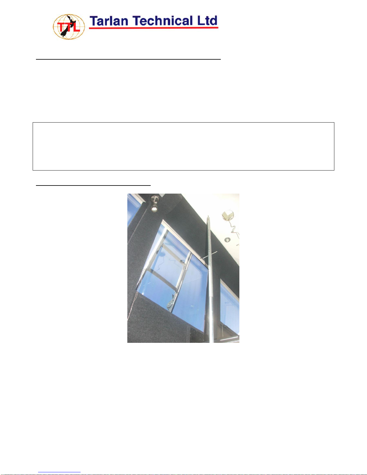
1. We use a modified expandable awning pole- place it in centre of fire outlet and extend to roof, align the
pole by eye with a vertical cabinet or door way on your interior, you can use a spirit level but check a
near surface to compare bus vertical level.
2. Once you have settled on the fire position and are confident the 150mm hole for the sleeve will be clear
of roof beams and wiring, and are confident you can reach the bolts when they protrude through the
floor( to get the nuts etc on) , mark the 4 holes for the fire.
3. Drill the 4 holes and use M10 high tensile bolts, add large square washers or steel plate on the bottom
side for the nuts to pull up on, if installation to floor is thought to be weak then add a chain to a
Page 5 of 18 Rev D May 2016
protruding bolt underneath floor and bolt other end of chain to the chassis. Remember fire is 42kg and
needs to secure in event of a sudden crash.
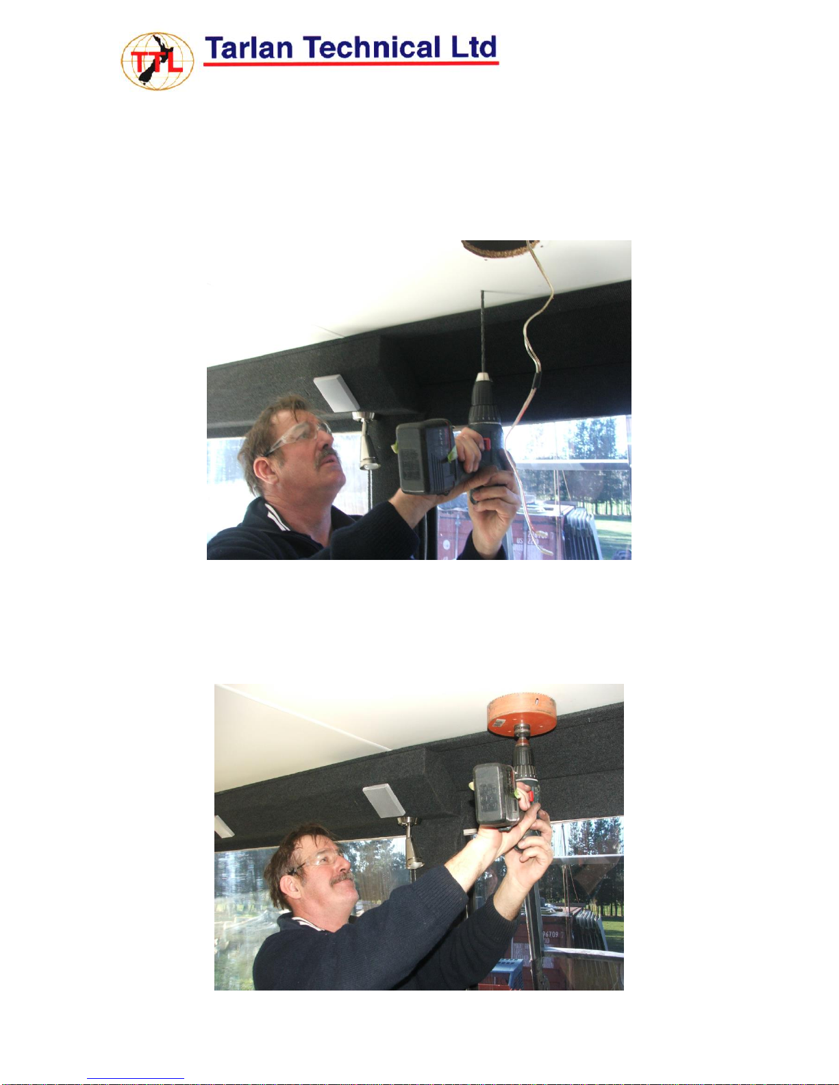
4. Mark the centre and drill a ¼ “ pilot hole through the two layers of the roof, you may need a long drill
(make sure drill is kept straight with the line the pole was, get an assistant to watch drill and make
corrections if needed)
Use any access such as the removed speaker in this photo to check what is in the roof lining, i.e. wires or
beams.
Page 6 of 18 Rev D May 2016
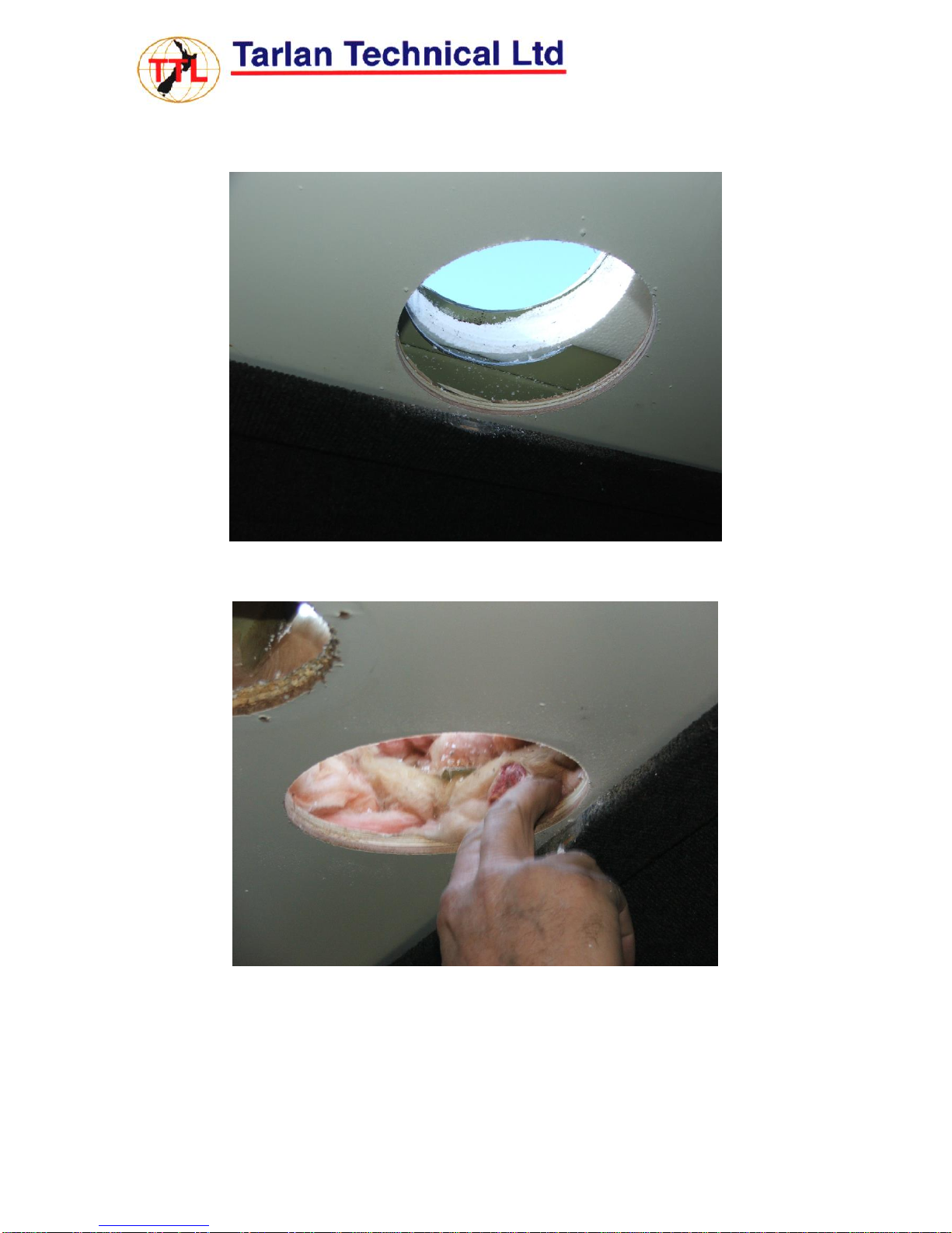
5. Use a 150mm hole saw or a jig saw to cut both surfaces, its best to drill the layers from each side, just
break through the first layer and check for wires etc.
Remove as much polystyrene as possible –at least 50mm from hole edge all way around.
Insert pink batts where the poly was removed

Page 7 of 18 Rev D May 2016
6. Fix SLEEVE to top roof by three metal tabs (not included - made up of any sheet metal 40mm x 15mm
wide is sufficient size, bend at centerline 90 deg) –check the sleeve it should be central and protrude
approx. 210 mm above roof. 80mm for the Dektite and 130mm to attach the top cowl.
We rivet a tab to sleeve at 210mm, keep seem of sleeve to rear side as shown here.
7. Slide the SLEEVE though the holes, a tip is to temporarily drop flue through the sleeve and lower into
fire. Use spacer as per step 11 to help centralize sleeve (Do not fit maniseal yet)
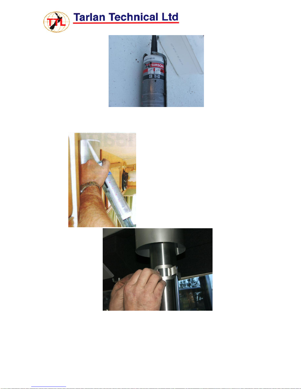
8. Apply sealant to outside joint around the 150mm liner. We recommend Simson ISR70-03, available in
black or grey (available Blacks Fasteners Ltd)
Page 8 of 18 Rev D May 2016
9. On inside surface if hole is a neat fit then apply a bead of sealant, no more gaps is ideal as can be
cleaned up with damp rag –white if it suits roof lining for a neat finish –enclosed is a ceiling plate in
case hole needs tidying up .
applying no more gaps giving clean finish
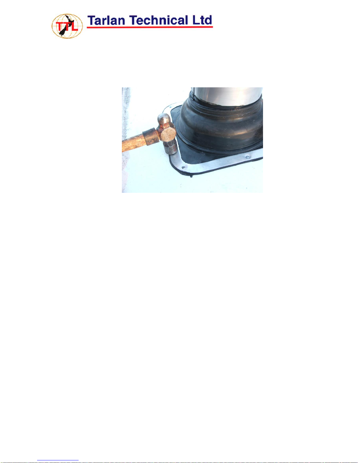
10. Bend to supplied spacer to shape –roll it around flue then bend the tabs out –then add spacer to hold
the flu and 150mm liner parallel to each other –fit this to flue and position it around 20mm from
bottom edge of the 150mm sleeve. (In this picture we assemble it, then slide it up inside the sleeve and
then tighten bolt) spacer comes as a flat unbent piece which needs to be bent by hand, bend the three
tabs out same way as end piece is bent, bed other end same direction –wrap around flue to curve it, fit
bolt
Page 9 of 18 Rev D May 2016
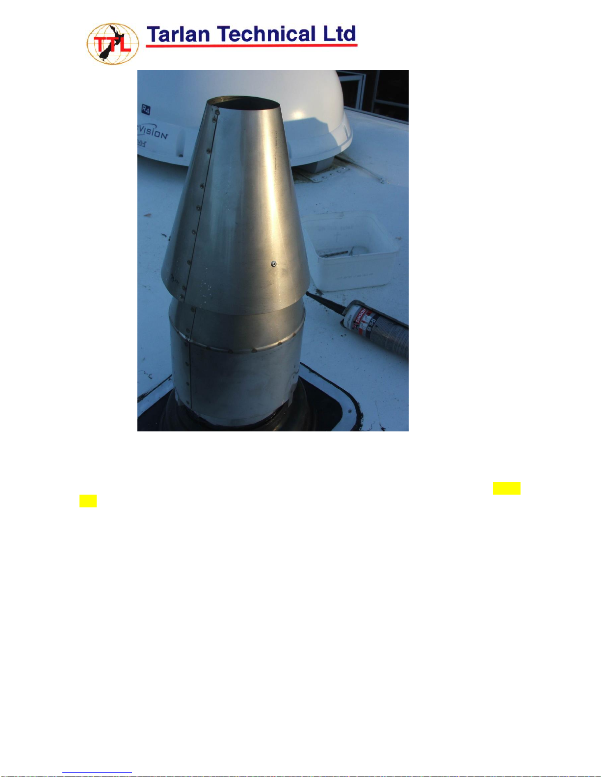
12. Cut the Dektite at the 140-150mm mark and fit, once positioned lift it up, put sealant under the top lip
and pull back down, then proceed to put sealant under the edge and rivet edge flange to roof.
Make sure sealant shows at edges, if it doesn’t apply a bead on the edge of it to the roof.
Also cover each rivet with sealant.
Page 10 of 18 Rev D May 2016
13 Trim FLUE TO FINISHED LENGTH measure from top of Dektite (highest point) and mark at 320
mm, (use an angle grinder with 1mm cut off disc)
14 Put Maniseal (available from auto parts store –Repco etc) around the flue below the rib and cover
inside of fire spigot,drop into fire (don’t do this if you are removing flue to cut to length, do it on last
fit) wipe Maniseal surplus off quickly with a wet/damp cloth
15 Put a bead of RTV of the very top lip of the flue (OUTSIDE OF FLUE) and fit cowl,(as also mentioned
below) check cowl is central and straight, and then put a rivet on each of the protruding legs at the
bottom of the cowl. Use 4mm stainless rivets
Otros manuales para Little Cracker
1
Tabla de contenidos


