T&C TC36.NG05.C Manual de usuario

290409-12 TC36.NG05.C 5056.427.C45
INSTALLER: Leave this manual with the appliance.
CONSUMER: Retain this manual for future reference.
These instructions are supplementary to the Installation and
Operating Instructions supplied with the replace and should be
kept together. Refer to the Installation and Operating Instructions
for proper gas supply, safety requirements and operating
instructions
TC36
HEARTWOOD
BURNER INSTALLATION
INSTRUCTIONS
PART#
TC36.NG05.C
FOR TC36 & TC36 AR
Series C
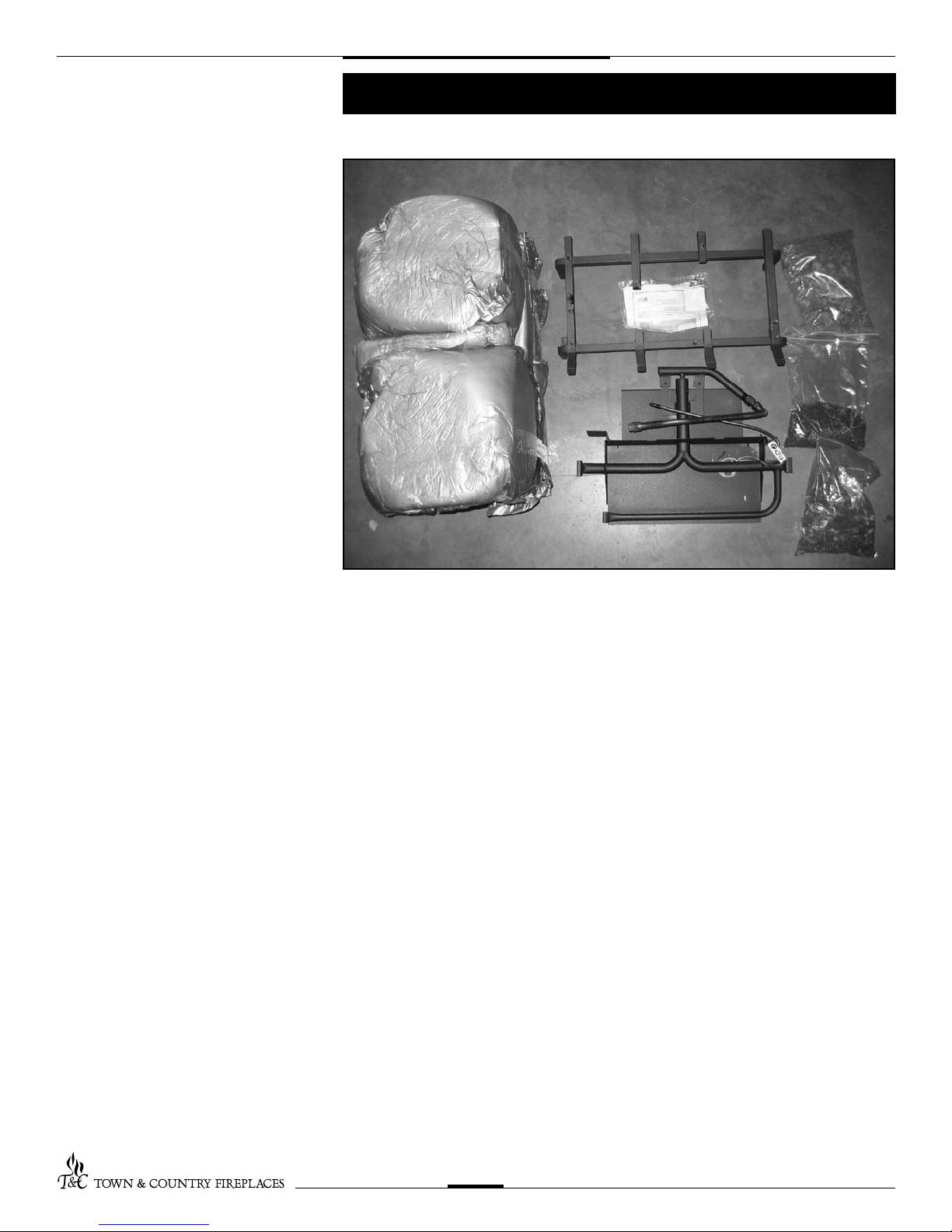
Contents of Package
2
TC36.NG05.C 290409-12
• BURNERASSEMBLY(includingpilotandmanifold)
• LOGGRATE
• TC36HEARTWOODLOGS
• EMBERMATERIAL
• HARDWAREPACKAGE
• AIRDEFLECTOR
• COALCHUNKS
• VERMICULITE

If this replace is to be
used on Propane please
convert prior to installtion.
See pages 6 – 8.
3
TC36.NG05.C 290409-12
1. Attachtheburnerassemblytotheoor
shield in the bottom of the rebox with
twoscrews.Ensurethatthefrontedge
oftheburnerisushwiththefrontofthe
shield.
(Fig.#1)
2. Attachsparkelectrode(ORANGE)and
sensor leads to the electrical bulk head.
(Fig.#2)(Thesparkelectrodeconnection
hasareddotaboveit).
3. Attachthepilotandgassupplytubes
to the bulk head tting and tighten.
(Fig.#3)Ensuretheconnectionsare
gas tight. Conceal the spark and sen-
sor wires below the supply tubes.
A panel set must now be installed.
See Installation and Operating
Instructions manual for details.
4. Positiontheslotsofthegratesecuring
bracketsovertheholesintheoorshield
and secure with the two screws.
(Fig.#4)
Fig. # 2
Fig. # 1
Fig. # 4
Fig. # 3
Burner Installation
Note:
Ember material placement
and amount will affect
ame appearance.
More ember material
results in lower ame
height.
Add or remove as needed
until desired ame affect.
Reduce the amount used
on Propane models, as too
much will create soot
4
TC36.NG05.C 290409-12
Fig. #5
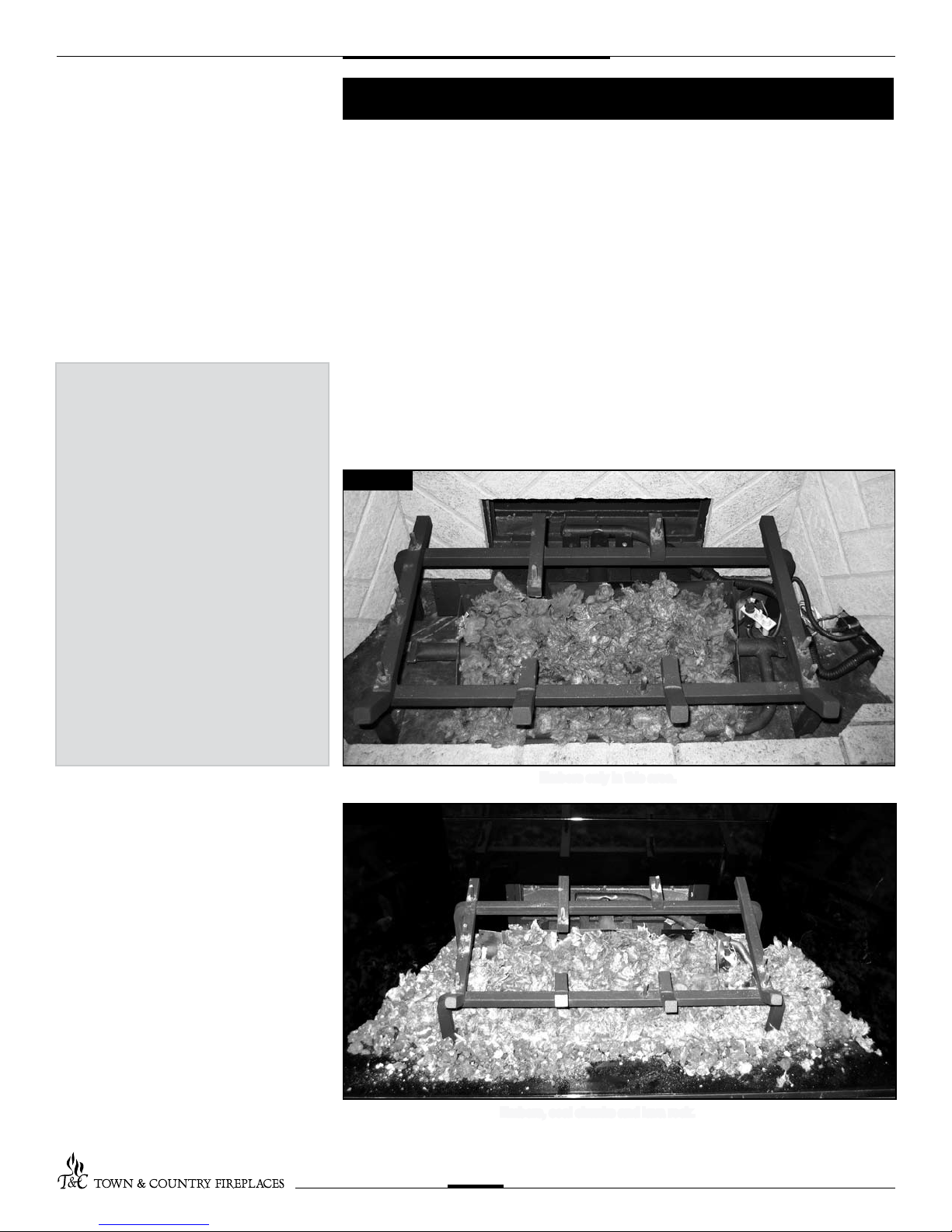
Ember Material
Fig. #6
Alargebagofembermaterialisshippedwiththereplaceandneedstobeinstalledon
theburnertoensureoptimumperformanceandameappearance.Abagofcoalchunks
and lava rock is also supplied this must only be used around the burner pan to cover up
the gas lines and brackets.
1. Pullapartthematerialintoembersizepieces(approximately1”squares)and
gentlyplacethemintotheburnerpan.Donotcompress,leavethemlooseforbest
performance.
2. Filltheburnerpanwithembersuntillevelwiththetopofthepanatrear,andgradually
slopeforwardtothereboxooratthefront,coveringbothburnertubes.
3. Placeremainingembermaterial,coalchunksandlavarockoutsideoftheburnerpan
as desired to cover-up gas lines and brackets. Do not put coal chunks or lava rock
inside burner pan as this will cause sooting and the burner to malfunction.
Embersonlyinthisarea.
Embers,coalchunksandlavarock.

5
TC36.NG05.C 290409-12
Fig. #9
Fig. #11 Fig. #12
Fig. #10
Fig. # 7
Gas plumbing and vent connections should be completed before proceeding.
Thelogsarefragile,andshouldbehandledwithcare.Unpackandinspectlogset.There
should be a total of seven logs.
Positionthelogsasindicatedbythefollowingpictures.Thesevenmainlogshaveholesand
/orpins.Engageeachpininthecorrespondingholes.Theremainingtwologsdonothave
holesorpins.Theyrestinposition.Locateasperthediagrams(g.#7-15)
Note: Improper placement of logs will cause sooting on internal parts and glass. The
logs may need to be repositioned slightly to avoid excessive ame impingement.
Log Placement
Fig. # 8
Fig. #14 Fig. #15
Fig. #13
BASE LOG, #1 LEFT CENTER LOG, #2 LEFT FRONT LOG, #3
LOG WITH HOLE, #4 RIGHT CENTER LOG, #5 FRONT RIGHT LOG, #6
CENTER TWIG, #8RIGHT BASE LOG, #7 CENTER BASE CHUNK, #9

Propane Conversion
If the unit is to be used on propane,
convert as follows using the compo-
nents supplied with this replace:
CAUTION
The gas supply and electrical power
must be shut off before proceeding
with the conversion.
Fig. # 17
Fig. # 18
Fig. # 16
WARNING
This conversion kit shall be
installed by a qualied
service agency in
accordance with the
manufacturer's instructions
and all applicable codes
and requirements of the
authority having
jurisdiction.
If the information in these
instructions is not followed
exactly, a re, explosion or
production of carbon
monoxide may result
causing property damage,
personal injury or loss of
life.
The qualied service
agency is responsible for
the proper installation of
this kit.
The installation is not
proper and complete un-
til the operation of the
converted appliance is
checked as specied in the
manufacturer's instructions
supplied with the kit.
Note:Factorysuppliedcomponentsmust
be used to ensure correct input.
Afterconversionconrmpropermanifold
pressure.
1. Ensuretheburner,pilotandgas
supply are turned off, and the
appliance has cooled.
2. Remove the two screws securing the
manifold assembly to the burner.
(Fig.#16)
3. Remove the manifold assembly from the
burner.(Fig.#17)
4. Witha½”wrenchremovethenaturalgas
orice(#30)andreplacewithpropane
orice(#45)(ourpart#5021.34)
(Fig.#18)
5. Fullyopentheprimaryairshutter.
6. Reinstall the manifold assembly and
airdeector.
6
TC36.NG05.C 290409-12

Minimum
rate screw
7. Witha7/16”wrenchloosenthepilothead
on the pilot assembly by a half-turn
(Fig.#19)
8. Slidethepilotadjustmentbandoverand
ensure that the hole in the orice band is
showing.(Fig.#20showsNGposition,
Fig.#21showsLPposition)
9. Remove the minimum rate screw located
in the valve.
(Fig.#22)
Fig. #21
Fig. # 22
Fig. # 19
Fig. # 20
7
TC36.NG05.C 290409-12
Minimum
rate screw

8
TC36.NG05.C 290409-12
Minimum
rate screw
NG LP
Fig #23
Fig #24
Fig #25
Fig #26
10. Replacetheminimumrate screwwiththe
one provided in the propane conversion
kitsuppliedwiththisreplace.Ensure
that the screw is fully installed.
(Fig.#23)
11. Pullofftherubbercapfromthetopof
thepressureregulator.(Fig.#24)
12. Pressdownonthecenterpostand
rotate 90°. The center post should
staydown.(Fig.#25).Replacethe
rubber cap.
13. Fill in the date and the name of the
person who performed the conversion
in the white area on the conversion
label. Peel off the protective backing
and apply the conversion label directly
over the gas specications on the rating
label.
14. Attachtheaccesspaneltothesideof
the rebox with the previously removed
screws.(Fig.#26)
Note:
Gasket must be installed with access
panel.

9
TC36.NG05.C 290409-12
1. Remove the plug from the manifold test
port. The plug is located between the
rightsidelintelandreboxside(bottom
port).(Fig.#27)
2. Thread the extension test tting into the
opentestport.(Fig.#28)
3. Attachapressuregaugeontothe
tting.
4. When testing is complete remove the
extension test tting and replace the
plug. Thread sealant will be required to
ensure a gas-tight connection.
Correct gas pressure requirement:
Supply Pressure Natural Gas Propane
(For purpose of input adjustment)
Minimum 5.0" WC 12.5" WC
Maximum 13.9" WC 13.9" WC
Manifold Pressure
Maximum 3.8" WC 11.0w" WC
Minimum 2.1" WC 5.5" WC
Note:To test the gas pressure, turn off the gas supply before removing the plug from
the supply pressure test port or manifold pressure test port.
Verify gas pressures with the replace lit and on the highest setting.
Fig #27
Fig #28
Gas Pressure Check

10
TC36.NG05.C 290409-12
Fig. # 29
The air shutter on the burner tube controls the primary combustion air to the gas burner
andispresetatthefactoryfornaturalgasfuel.Someadjustmentmaybenecessaryto
obtaindesiredameandtoeliminatecarbondeposits.Evaluateameappearanceafter
thereplacehasreachedoperatingtemperature.SeeFig.#29forproperamepattern.
Open primary air shutter if the logs, glass, and rebox have carbon accumulation and /
ortheamesarelong,darkandstringy.Theshuttermayalsobeopenedtoenhancethe
EmberMaterialglowandlessentheameheight.
Caution: Burner area may be hot!
Turn off the replace and allow the unit to cool before proceeding.
Caution: Proper air shutter setting is a
must.
Theameshouldbe just orange and“lazy”.
ItshouldNEVERbesettocreatesootingon
internal parts and glass.
Flame Adjustment
To Adjust:
1. Open and remove window frame and set
aside.See"WindowFrameRemoval"sec-
tion found in the Installation and Operating
Instructions manual.
2. Remove the log set and set aside.
3. LoosenthescrewinthePrimaryAirShut-
ter.
4. Rotate the shutter to increase or decrease
the amount of primary air.
5. Reassemble in reverse order.
Fig. # 31
PRIMARY AIR SHUTTER
Tabla de contenidos
Otros manuales de Quemador de T&C


