Sylvania DVR90VE Manual de usuario

SUPPLEMENT
SERVICE MANUAL
DVD RECORDER &
VIDEO CASSETTE RECORDER
DVR90VE
DUBBING
CHANNEL
VCR
RECORD
OPEN/CLOSE
PLAYREWPOW ER F.F WD STOP/EJECT
OUTPUT SELECT
VCR DVD
STOP PLAY
DVD
RECORD
S-VIDEO VIDEO L - AUDIO - R
This service manual supplement is for
the DVR90VE W1.5 Version model,
which are different from previous
DVR90VE model.
For DVR90VE W1.5 Version model,
FUNAI model number (E9510UD) is
printed on rating label in the rear. Refer
to the rating label illustration at right.
This service manual shows only the
differences between the model DVR90VE W1.5 Version and the
original model EWR20V4 W1.5 Version.
All other information is described in the service manual of the
model EWR20V4 W1.5 Version.
FUNAI model number
rating label
VIDEO CASSETTE RECORDER/DVD RECORDER
MODEL NO. DVR90VE
MANUFACTURED:U
FUNAI CORPORATION INC.
100 NORTH STREET TETERBORO, NJ 07608
MARCH
2004
Tested To Comply With FCC Standards
FOR HOME OR OFFICE USE
E9510UD

IMPORTANT SAFETY NOTICE
Proper service and repair is important to the safe, reliable operation of all
Funai Equipment. The service procedures recommended by Funai and
described in this service manual are effective methods of performing service
operations. Some of these service special tools should be used when and as
recommended.
It is important to note that this service manual contains various CAUTIONS
and NOTICES which should be carefully read in order to minimize the risk of
personal injury to service personnel. The possibility exists that improper ser-
vice methods may damage the equipment. It also is important to understand
that these CAUTIONS and NOTICES ARE NOT EXHAUSTIVE. Funai could not
possibly know, evaluate and advice the service trade of all conceivable ways
in which service might be done or of the possible hazardous consequences
of each way. Consequently, Funai has not undertaken any such broad evalua-
tion. Accordingly, a servicer who uses a service procedure or tool which is
not recommended by Funai must first use all precautions thoroughly so that
neither his safety nor the safe operation of the equipment will be jeopardized
by the service method selected.
TABLE OF CONTENTS
Block Diagrams . . . . . . . . . . . . . . . . . . . . . . . . . . . . . . . . . . . . . . . . . . . . . . . . . . . . . . . . . . . . . . . . . . . . . . . . 1-1-1
Schematic Diagrams / CBA’s and Test Points. . . . . . . . . . . . . . . . . . . . . . . . . . . . . . . . . . . . . . . . . . . . . . . . . 1-2-1
Wiring Diagram < VCR Section > . . . . . . . . . . . . . . . . . . . . . . . . . . . . . . . . . . . . . . . . . . . . . . . . . . . . . . . . . . 1-3-1
Wiring Diagram < DVD Section > . . . . . . . . . . . . . . . . . . . . . . . . . . . . . . . . . . . . . . . . . . . . . . . . . . . . . . . . . . 1-3-2
Different parts from original model (EWR20V4 W1.5 Version) . . . . . . . . . . . . . . . . . . . . . . . . . . . . . . . . . . . . 1-4-1
Manufactured under license from Dolby Laboratories. "Dolby" and
the double-D symbol are trademarks of Dolby Laboratories.
1-1-1
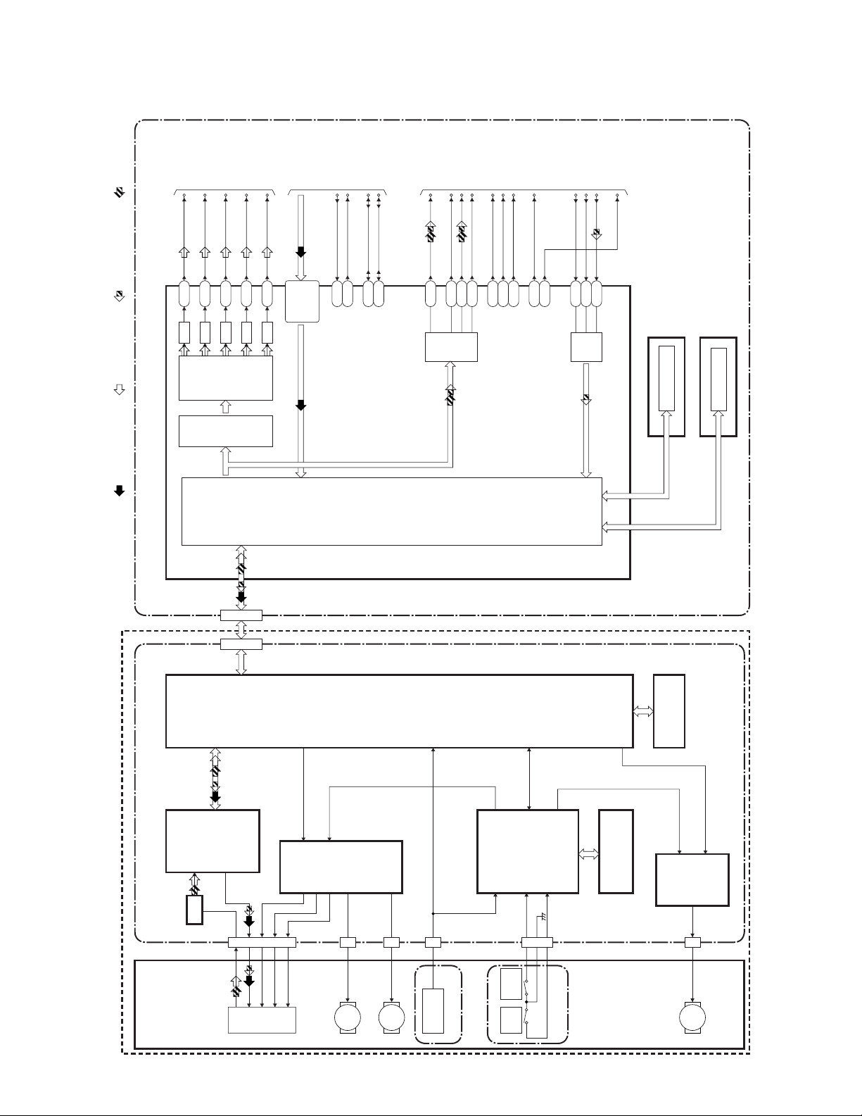
Digital Signal Process Block Diagram
E9510BLD
IC3 (MAIN MICRO CONTRLLER)IC5301
IC5401
FRONT-END
DIGITAL
SIGNAL
PROCESS
IC5202
RF/
ERROR
AMP
IC5501
MOTOR
DRIVER
MOTOR
DRIVER
IC5703
FRONT-END
MICRO
CONTROLLER
SDRAM
IC5503
IC6 (FLASH MEMORY)
DVD BE MAIN CBA UNITDVD FE MAIN CBA UNIT
TO VIDEO
INPUT SELECT
BLOCK DIAGRAM
TO AUDIO
INPUT/OUTPUT
SELECT
BLOCK DIAGRAM
TO VIDEO
OUTPUT SELECT
BLOCK DIAGRAM
SPDIF
BCK
DATA
LRCK
MD
MC
SCK
ML
MD
MC
SCK
ML
BCK
DATA
LRCK
SYSCLK
SYSCLK
AB23
AE12
AC13
AD12
AE13
AD21
E25
Y4
AD2
AD25
AC25
AB22
H24
J22
J23
AC23
AB20
AB21
AD24
AB19
VIDEO-Y(I/P)
VIDEO-C
VIDEO-Cb
VIDEO-Cr
Y
C
Cb
Cr
VID(0-7)
S-CLK
IC9-RESET
S-CLK
IC9-RESET
SCL
SDA
SCL
SDA
IC5704
FLASH
MEMORY
D/A
D/A
D/A
D/A
AUDIO
I/F
VIDEO
ENCODER
BACK-END
DIGITAL
SIGNAL
PROCESS
VIDEO
I/F
CN1CN5301
AUDIO
I/F
FLASH MEMORY
FE
ENCODER
TRAY
OPEN
TRAY
CLOSE
IC1,IC2 (DDR SDRAM)
DDR SDRAM
AC19,AE22,
AE23,AC20,
AC21,AB18,
AD22,AF24
CN5501
CN5101
CN5603B
DVD MECHA
TILT
TRACKING
FOCUS
PICK
-UP
CN5502B
CN5603
CN5602B
LOADING
MOTOR
M
SLED
MOTOR
M
SPINDLE
MOTOR
M
REC VIDEO SIGNAL PB VIDEO SIGNAL REC AUDIO SIGNAL PB AUDIO SIGNAL
LOADER CBA
ENCODER CBA
DVD MECHA & FE ASSEMBLY
AC12 VIDEO-Y(I)
Y(I)
D/A
IC5203,
IC5204
SW
BLOCK DIAGRAMS

1-1-2
Video Output Select Block Diagram
E9510BLVOS
DVD BE MAIN CBA UNIT MAIN CBA
CN7
14 14
VIDEO-Y(I/P)
16 16VIDEO-C
12 12VIDEO-Cb
10 10VIDEO-Cr
VIDEO-Y(I/P)
VIDEO-C
VIDEO-Cb
VIDEO-Cr
JK1401
S-VIDEO
OUT
CN201
3 4
2
1
IC1405 (VIDEO DRIVER)
R1402
4dB
AMP
2dB
AMP
LPF DRIVER YC
8dB
AMP
-6dB DRIVER
IC1406
(OUTPUT SELECT)
4dB
AMP
2dB
AMP
LPF DRIVER
11
4dB
AMP
2dB
AMP
LPF DRIVER
6
10
4dB
AMP
2dB
AMP
LPF
MUTE
DRIVER
8
5
VIDEO-Cb
OUT
VIDEO-Y
OUT
VIDEO-Cr
OUT
JK1403
COMPOSITE
VIDEO OUT
JK751
TP751
V-OUT
3
115
TO DIGITAL SIGNAL
PROCESS BLOCK
DIAGRAM
V-MUTE
DVD-VIDEO(DUB)
SW CTL
PB/EE-VIDEO
TO SUB SYSTEM
CONTROL
BLOCK DIAGRAM
TO SERVO/SYSTEM CONTROL
BLOCK DIAGRAM
TO VIDEO
BLOCK DIAGRAM
REC VIDEO SIGNAL PB VIDEO SIGNAL
WF4
WF5
WF6
WF7
WF8
2
15
1
109 11
OUTPUT-SELECT
Q391
BUFFER
TU900 (TUNER UNIT)
6
VIDEO-IN
(DVD VCR DUBBING)
WF1
WF12
IC1404 (VIDEO DRIVER)
5
4dB
AMP
2dB
AMP
LPF DRIVER
6
8dB
AMP
-6dB DRIVER
4dB
AMP
2dB
AMP
LPF DRIVER
3
17
11VIDEO-Y(I)
VIDEO-Y(I)
R1410
14
13

1-2-1 W1-SC
SCHEMATIC DIAGRAMS / CBA’S AND TEST POINTS
Standard Notes
WARNING
Many electrical and mechanical parts in this chassis
have special characteristics. These characteristics
often pass unnoticed and the protection afforded by
them cannot necessarily be obtained by using replace-
ment components rated for higher voltage, wattage,
etc. Replacement parts that have these special safety
characteristics are identified in this manual and its
supplements; electrical components having such fea-
tures are identified by the mark " #" in the schematic
diagram and the parts list. Before replacing any of
these components, read the parts list in this manual
carefully. The use of substitute replacement parts that
do not have the same safety characteristics as speci-
fied in the parts list may create shock, fire, or other
hazards.
Notes:
1. Do not use the part number shown on these draw-
ings for ordering. The correct part number is shown
in the parts list, and may be slightly different or
amended since these drawings were prepared.
2. All resistance values are indicated in ohms
(K=103, M=106).
3. Resistor wattages are 1/4W or 1/6W unless other-
wise specified.
4. All capacitance values are indicated in µF
(P=10-6 µF).
5. All voltages are DC voltages unless otherwise
specified.

1-2-2 SC_09
A V
F
LIST OF CAUTION, NOTES, AND SYMBOLS USED IN THE SCHEMATIC DIAGRAMS ON THE FOLLOWING
PAG ES:
1. CAUTION:
FOR CONTINUED PROTECTION AGAINST FIRE HAZARD, REPLACE ONLY WITH THE SAME
TYPE FUSE.
ATTENTION: POUR UNE PROTECTION CONTINUE LES RISQES D'INCELE N'UTILISER QUE
DES FUSIBLE DE MEMO TYPE.
RISK OF FIRE-REPLACE FUSE AS MARKED.
2. CAUTION:
Fixed Voltage (or Auto voltage selectable) power supply circuit is used in this unit.
If Main Fuse (F1001) is blown, first check to see that all components in the power supply circuit are not defective
before you connect the AC plug to the AC power supply. Otherwise it may cause some components in the
power supply circuit to fail.
3. Note:
(1) Do not use the part number shown on the drawings for ordering. The correct part number is shown in the parts
list, and may be slightly different or amended since the drawings were prepared.
(2) To maintain original function and reliability of repaired units, use only original replacement parts which are
listed with their part numbers in the parts list section of the service manual.
4. Mode: SP/REC
5. Voltage indications for PLAY and REC modes on the schematics are as shown below:
6. How to read converged lines
7. Test Point Information
This symbol means fast operating fuse.
Ce symbole represente un fusible a fusion rapide.
231
5.0
(2.5)
PLAY mode
STOP mode
5.0
The same voltage for
both PLAY & STOP modes Indicates that the voltage
is not consistent here.
< DVD Section >
231
5.0
(2.5)
< >
PLAY mode
REC mode
DVD mode
5.0
The same voltage for
both PLAY, REC & DVD
modes Indicates that the voltage
is not consistent here.
< VCR Section >
Unit: Volts
1-D3
Distinction Area
Line Number
(1 to 3 digits)
Examples:
1. "1-D3" means that line number "1" goes to area "D3".
2. "1-B1" means that line number "1" goes to area "B1".
3
2
1
ABCD
1-B1
1-D3
AREA D3
AREA B1
: Indicates a test point with a jumper wire across a hole in the PCB.
: Used to indicate a test point with a component lead on foil side.
: Used to indicate a test point with no test pin.
: Used to indicate a test point with a test pin.

DD1
DD2
DD3
EE1
EE2
EE3
FF1
FF2
FF3
GG1
GG2
GG3
HH1
HH2
HH3
DD4 EE4 FF4 GG4 HH4
II1
II2
II3
II4
PB VIDEO SIGNAL
PB AUDIO SIGNAL
REC AUDIO SIGNAL
REC VIDEO SIGNAL
Main 6/8 Schematic Diagram < VCR Section >
1-2-3 1-2-4 E9510SCM6
MAIN 6/8
RefNo. Position
IC800 EE-2
IC801 GG-2
IC803 HH-1
IC805 EE-3
IC900 FF-3
Q200 GG-1
Q201 GG-1
Q800 FF-3
Q801 FF-2
CN201 II-2
CN1609 DD-1
TRANSISTORS
ICS
CONNECTORS

JJ1
JJ2
JJ3
KK1
KK2
KK3
LL1
LL2
LL3
MM1
MM2
MM3
NN1
NN2
NN3
JJ4 KK4 LL4 MM4 NN4
OO1
OO2
OO3
OO4
PB VIDEO SIGNAL
PB AUDIO SIGNAL
PB Audio Signal (Digital)
MAIN 7/8
RefNo. Position
IC804 KK-1
IC1404 LL-4
IC1405 LL-4
IC1406 LL-2
Q391 MM-2
Q802 JJ-2
Q804 LL-1
Q805 LL-1
Q806 LL-1
Q1351 MM-1
TP751 OO-4
TP753 NN-4
TP754 NN-4
TEST POINTS
ICS
TRANSISTORS
REC AUDIO SIGNAL
REC VIDEO SIGNAL
REC Audio Signal (Digital)
Main 7/8 Schematic Diagram < VCR Section >
1-2-5 1-2-6 E9510SCM7

A1
A2
A3
A4
B1
B2
B3
B4
C1
C2
C3
C4
D1
D2
D3
D4
E1
E2
E3
E4
F1
F2
F3
F4
PB Audio Signal
PB Video Signal
PB Video Signal (Digital)
PB Video+Audio Signal (Digital)
PB Audio Signal (Digital)
REC Audio Signal
REC Video Signal
REC Video Signal (Digital)
REC Video+Audio Signal (Digital)
REC Audio Signal (Digital)
DVD BE Main 1/4 Schematic Diagram < DVD Section >
1-2-7 1-2-8 E9510SCBM1
Note:
1. The order of pins shown are different from that of IC3 itself.
2. IC3 is shown as IC3(1/6) through IC3(6/6) in DVD BE Main Schematic Diagram section.
DVD BE MAIN 1/4
Ref No. Position
IC3(1/6) D-3
IC9 B-4
IC12 B-2
IC13 D-1
IC17 C-4
Q16 D-4
Q17 D-4
Q18 E-4
Q19 B-4
Q20 A-4
Q21 E-2
CN7 F-4
ICS
CONNECTOR
TRANSISTORS
G1
G2
G3
G4
H1
H2
H3
H4
I1
I2
I3
I4
J1
J2
J3
J4
K1
K2
K3
K4
L1
L2
L3
L4
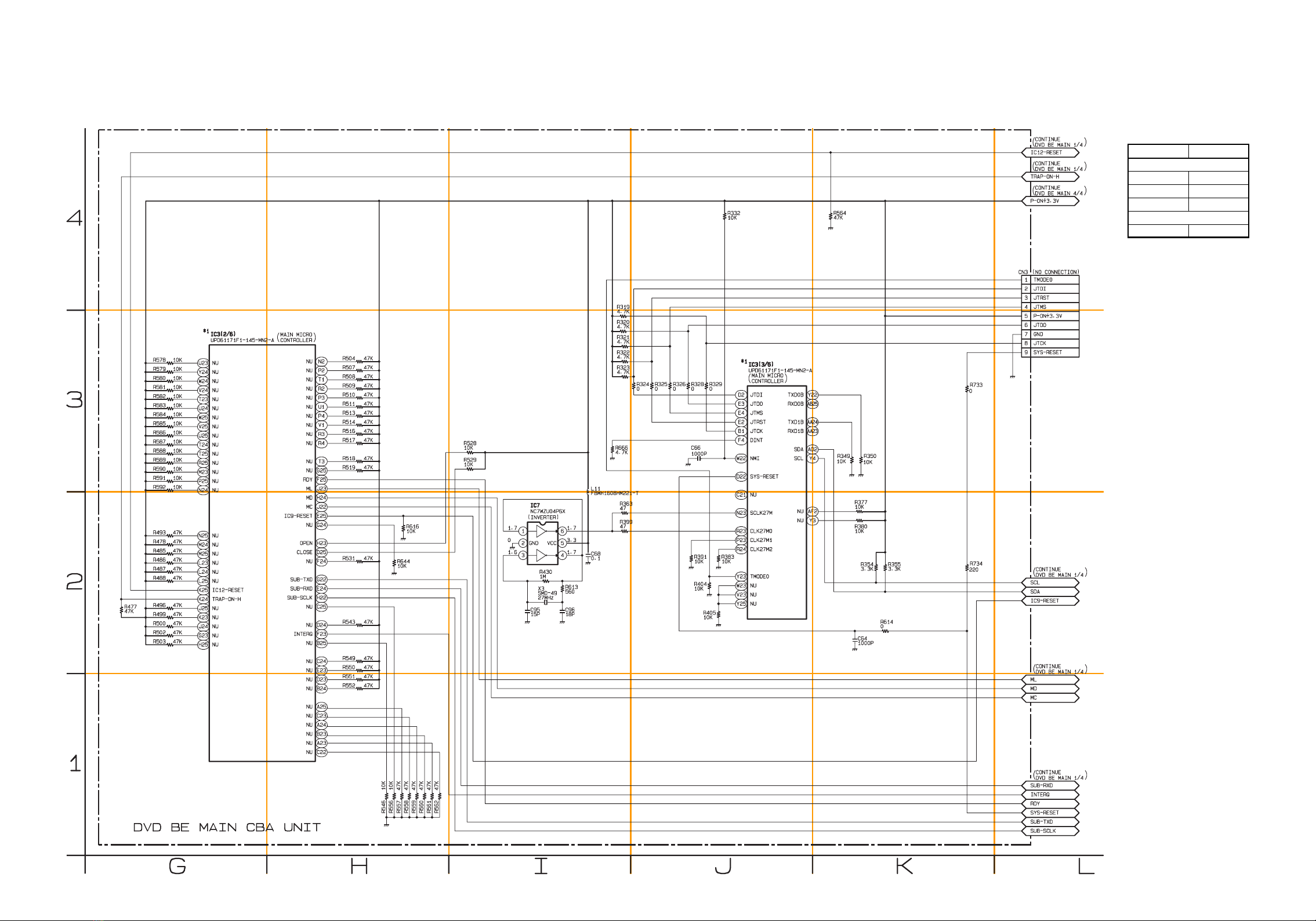
DVD BE Main 2/4 Schematic Diagram < DVD Section >
1-2-9 1-2-10 E9510SCBM2
Note:
1. The order of pins shown are different from that of IC3 itself.
2. IC3 is shown as IC3(1/6) through IC3(6/6) in DVD BE Main Schematic Diagram section.
DVD BE MAIN 2/4
Ref No. Position
IC3(2/6) G-3
IC3(3/6) J-3
IC7 I-2
CN3 L-4
ICS
CONNECTOR
Otros manuales para DVR90VE
1
Este manual sirve para los siguientes modelos
2
Tabla de contenidos
Otros manuales de Grabadora de voz de Sylvania


