Sylvac D300S V2 Manual de usuario

User guide
Manuel d’utilisation
Bedienungsanleitung
E
F
D
Software version V2.00
OS V2.00
Universal display unit
Unité d’affichage universelle
Universelle Anzeigeeinheit


3
Summary
General Description 4
Front panel 4
Back panel 4
Connections description 5
Input / Output explanations 6
USB Host 6
USB Device 6
Power Switch 6
Sustain pedal input 6
Network connection (RJ45) 6
Speakers (Jack) 6
VGA Output 6
RS485 7
RS232 7
Probe input 7
Digital outputs 8
Example to connect a LED on the no1 digital output 8
Example to connect a relay on the no1 digital output 8
Example to connect an external contact on a Switch 1 input 9
RS485/D30X and RS485/MB-X connections 9
User interface 10
The setting menu 10
The setting menu tree 11
General setting 12
Channel setting 12
Channel allocation 12
Exclude from automatic detection 13
Tolerance mode 13
Number of classes 13
Display mode 13
Measurement mode 13
Channel calibration at 2 points 14
System setting 14
Digital outputs 14
External contact 15
Printing 16
&RQ¿JXUDWLRQRIVHTXHQFHV
List of instruments 18
General tolerance 19
Calibration 19
Hot Keys 20
Statistics 21
The histogram 21
The chart of the average (Xbar) 21
The chart over the range (R) 22
The statistics table 22
Communication with a PC 23
Communication example with Winwedge 32 software 23
Retro-command codes list 24
Network connection 26
&RQ¿JXUDWLRQH[DPSOHZLWKWZRPHDVXUHPHQWSRLQWV
([DPSOHRIFRQ¿JXUDWLRQZLWKWKUHH%OXHWRRWKLQVWUXPHQWV
E

4
The D300S is a display unit enabling the visualisation of the entire Sylvac hand
instrument range and P2, P5, P10, P25, P50 probes. The intuitive interface
HQDEOHVWKHXVHUWRHDVLO\FRQ¿JXUHWKHGHYLFHDQGVROYHPRVWPHDVXUHPHQW
problems met in production or in laboratory.
12
7
1 3 4
6
5
17 1618
9
2
13
10
11
8
1415
19
General description
Front panel
Back panel

5
1
2
3
4
5
6
7
8
9
10
11
12
13
14
15
16
17
18
19
8.5’’ touch screen
&RQ¿JXUDEOHXVHULQWHUIDFH
IP65 front panel
Navigation buttons
Numeric keypad
Standby button
Master switch for the unit
Connector for 24V power supply
USB ports for SYLVAC instruments, keyboard or mouse
USB port D300S -> PC
LAN port
SYLVAC probe inputs (4-input module available)
Digital inputs/outputs
External contacts (pedals, limit switch etc.)
Jack socket for speakers
VGA output
RS485 connector for connecting D302/D304 units
RS232 input for SYLVAC instrument
RS485 connector for connecting MB-8i / MB-2C /
MB-4C / MB-2S units (only available on certain versions)
E
Connections description

6
Input/output explanations
86%+RVW
Enables measurements sending to a PC. Depending on the operating system,
DGULYHUPD\EHUHTXLUHG,WFDQEHGRZQORDGHGGLUHFWO\IURPWKHZZZIWGLFKLS
com website.
The default communication parameters are as follows:
Baud Rate 4800
Parity Even
Data Bits 7
Stop Bits 2
Flow Control None
The list of retro-commands recognised by the D300S are found in the « Retro-
command codes list » chapter, P. 24.
86%'HYLFH
Enables the connection of measurement instruments through a usb cable
(Proximity-USB, Opto-USB, Power-USB, …). It is possible to extend the num-
ber of USB ports using a usb hub.
30 USB instruments at the most can be connected at the same time.
Power Switch
Allows the complete switching off of the unit
Sustain pedal input
Two pedals can be connected. Two extra external contacts are also available on
the screw terminal (Switch 1 and 2).
Network connection (RJ45)
The connection to a local network enables amongst other things the retrieval of
UHFRUGHGGDWDH[UHFRUGHGPHDVXUHPHQWVFRQ¿JXUDWLRQ¿OHV
Speakers (Jack)
Input enabling the connection to a speaker.
VGA output
Enables the connection of the D300S to an external screen or projector.
Note : The resolution stays identical to the unit's one, i.e. 800x400. It cannot be
PRGL¿HG
7
E
RS485
Enables the connection of the D302 and D304 probe modules.
RS232
Enables the connection of a RS232 instrument with a Duplex cable.
Probe input
Enables the connection of the Sylvac probes (P2, P5, P10, P25, P50).
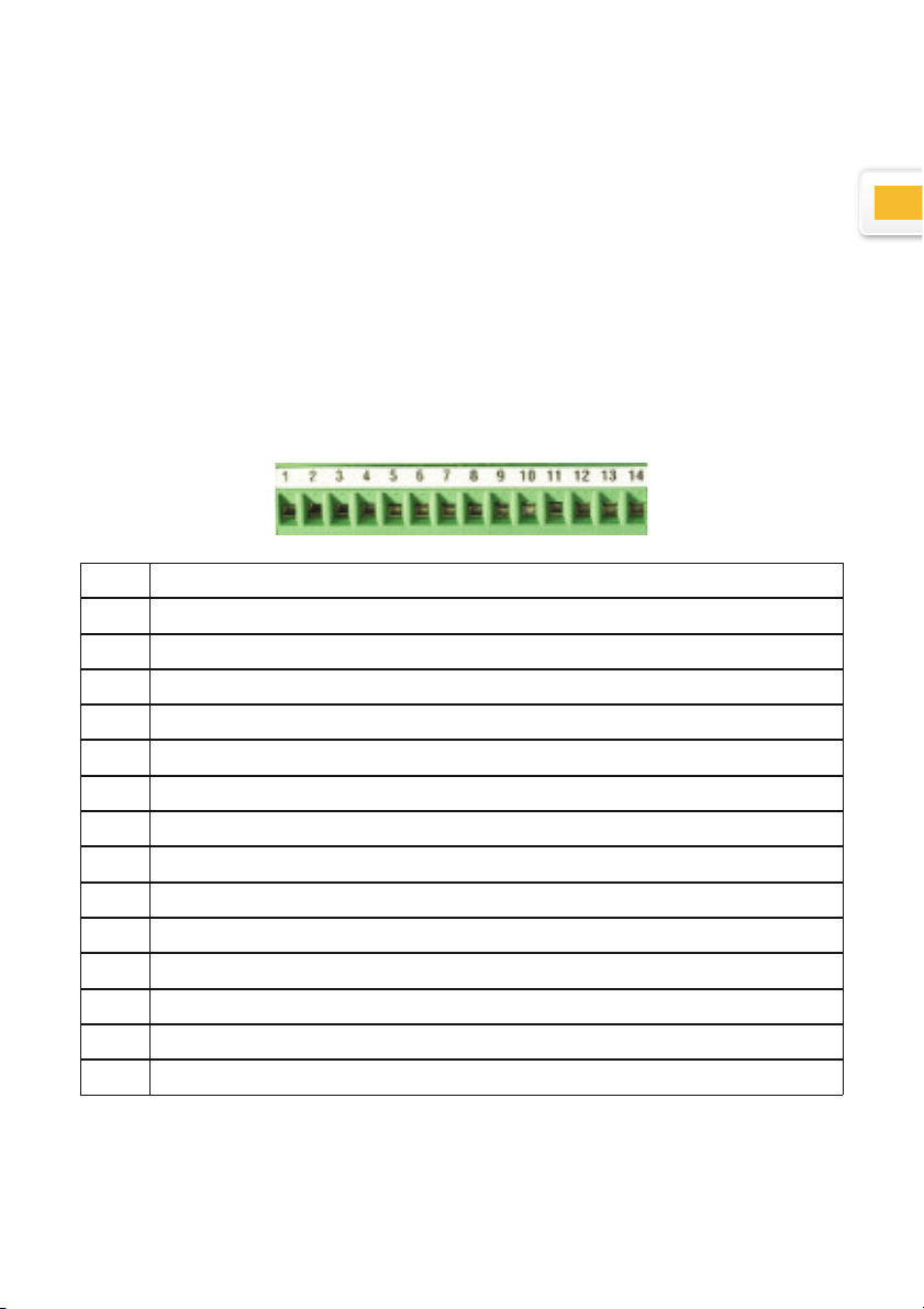
Digital outputs
N° Function
1 Output isolated by optocoupler
2 Output isolated by optocoupler
3 Output isolated by optocoupler
4 Output isolated by optocoupler
5 Output isolated by optocoupler
6 Output isolated by optocoupler
7 Output isolated by optocoupler
8 Output isolated by optocoupler
9 Common for the 8 optocoupler outputs
10 Switch 1
11 Switch 2
12 External power supply +24V (input)
13 GND
14 Internal power supply +24V (output)

8
R
Schematic representation
The maximum voltage is 30V
and the maximum current is
60mA per output.
The supply voltage of the
optocoupler outputs are nor-
mally brought from the out-
side, the negative pole on
the common transmitters
(pin 9)
The protective diode is indis-
pensable in case of inductive
load (solenoid valve, relay,
...)
Example to connect a LED on the n°1 digital output
Example to connect a relay on the n°1 digital output
(external power supply)
External power supply (max. +30V)
GND's external power supply
COM
NO NC
Note: a protective diode must be added in parallel of the relay if it isn't integrated.

9
E
Example to connect a relay on the n°1 digital output
(internal power supply)
COM
NO NC
Note: a protective diode must be added in parallel of the relay if it isn't integrated.
Example to connect an external contact on the Switch 1 input
RS485/D30X and RS485/MB-X connections
These two inputs allow an increase in the number of probes connected to the
D300S.
Remark :WKHFRQ¿JXUDWLRQMXPSHUVPXVWEHSODFHGRQ-3DQG-3VRWKDWWKH
module is correctly detected by the D300S.
7KH560%;LQSXW(only available on certain versions)
This input is used to connect the MB-8i, MB-2C, MB-4C or even MB-2S type
modules. Inductive capacitive and incremental probes can be connected to
these modules.
7KH56';LQSXW
This input is exclusively used for the
D302 and D304 modules.
The capacitive probes (P5, P10,
P25, P50) can be connected to these
modules.

10
1
3 4 5 6
10
11
12
8
2
7 9 13
Window showing details of channel X
Active page indicator
Select page X/X
&RQ¿JXUDWLRQRIQXPEHURISDJHVPD[
*HQHUDOFRQ¿JXUDWLRQ
Display type (shift to static mode)
Channel individual preset
Channel reset
&KDQQHOFRQ¿JXUDWLRQ
Measurement recording (of the active page)
Clear all displayed channels
Preset all displayed channels
Activate the Min/Max extent
1
2
3
4
5
6
7
8
9
10
11
12
13
User interface
While the unit switches off, all parameters are automatically saved. It is also
SRVVLEOHWRVDYH\RXUFRQ¿JXUDWLRQVLQRUGHUWRXVH\RXU'6IRUVHYHUDOGLI-
ferent workstations.
When an instrument is connected, it is automatically assigned a channel. The
FDEOH¶VLGHQWL¿FDWLRQDGGUHVVLVUHJLVWHUHGE\WKHXQLW
It is therefore vital not to switch it with other instruments. If you disconnect the
cable from the unit and use a different USB port when you next connect it, the
same channel will be reassigned to it.
The Setting menu
This menu enables the modification of all system parameters.
:KHQ\RX¿UVWVZLWFKRQ\RXU'6XQLWWKHGHIDXOWLQWHUIDFHZLOOEHDFWLYHDV
shown below.
Tabla de contenidos
Idiomas:
Otros manuales de Monitor de Sylvac


