SUTO S217 Manual
English
Instruction and operation manual
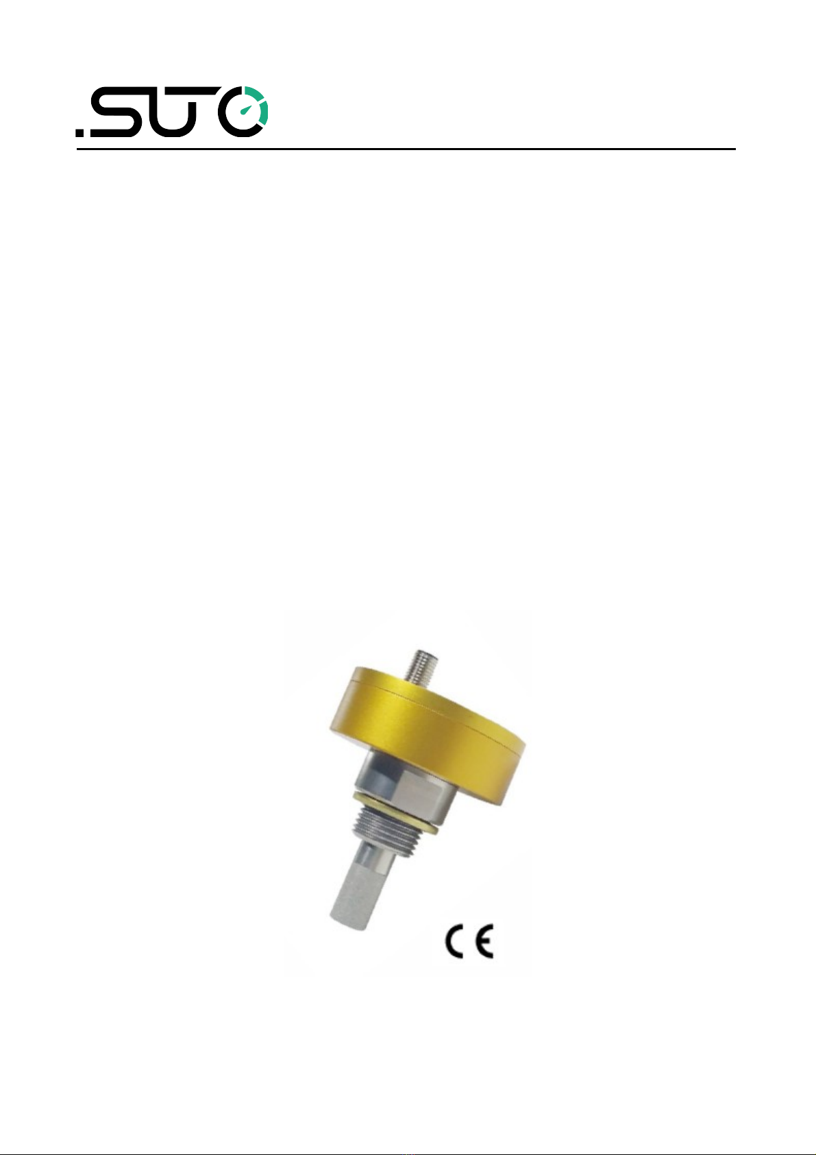
S217
Dew point sensor

Dear Customer,
Thank you for choosing our product.
The operating instructions must be read in full and carefully observed
before you start up the device. The manufacturer cannot be held liable
for any damage which occurs as a result of non-observance or non-
compliance with this manual.
Should the device be tampered with in any manner other than a
procedure which is described and specified in the manual, the warranty
is void and the manufacturer is e empt from liability.
The device is destined e clusively for the described application.
SUTO offers no guarantee for the suitability for any other purpose.
SUTO is also not liable for consequential damage resulting from the
delivery, capability or use of this device.
2 S217

Safety instructions
Table of contents
1 Safety instructions.......................................................................4
2 Registered trademarks.................................................................6
3 Application..................................................................................7
4 Features.....................................................................................7
5 Technical data.............................................................................8
5.1 General................................................................................8
5.2 Accuracy ..............................................................................8
6 Dimensional drawing....................................................................9
7 Electrical connection .................................................................10
8 Modbus output (S217-8 and S217-9)...........................................11
8.1 Modbus holding register table................................................11
8.2 Byte ordering and byte sequencing.........................................13
8.3 Interpretation of system status..............................................13
9 Installation ...............................................................................14
9.1 Installation requirements......................................................14
9.2 Installation procedure ..........................................................14
9.3 Order information................................................................16
10 Calibration..............................................................................17
11 Maintenance............................................................................17
12 Disposal or waste.....................................................................17
S217 3

Safety instructions
1 Safety instructions
Please check if this instruction manual matches with the
product type.
Please observe all notes and instructions indicated in this
manual. It contains essential information which must be
observed before and during installation, operation and
maintenance. Therefore this instruction manual must be read carefully
by the technician as well as by the responsible user / qualified
personnel.
This instruction manual must be available at the operation site of the
dew point sensor at any time. In case of any obscurities or questions,
regarding this manual or the product, please contact the manufacturer.
W RNING!
Compressed air!
ny contact with quickly escaping air or bursting
parts of the compressed air system can lead to
serious injuries or even death!
•Do not e ceed the ma imum permitted pressure range (see
sensors label).
•Only use pressure tight installation material.
•Avoid that persons get hit escaping air or bursting parts of the
instrument.
•The system must be pressureless during maintenance work.
W RNING!
Voltage used for supply!
ny contact with energized parts of the product, may
lead to a electrical shock which can lead to serious
injuries or even death!
•Consider all regulations for electrical installations.
•The system must be disconnected from any power supply during
maintenance work.
•Any electrical work on the system is only allowed by authorized
qualified personal.
4 S217

Safety instructions
TTENTION!
Permitted operating parameters!
Observe the permitted operating parameters, any
operation exceeding this parameters can lead to
malfunctions and may lead to damage on the
instrument or the system.
•Do not e ceed the permitted operating parameters.
•Make sure the product is operated in its permitted limitations.
•Do not e ceed or undercut the permitted storage and operation
temperature and pressure.
General safety instructions
•It is not allowed to use the product in e plosive areas.
•Please observe the national regulations before/during installation
and operation.
Remarks
•It is not allowed to disassemble the product.
•Always use spanner to mount the product properly.
TTENTION!
Measurement values can be affected by malfunction!
The product must be installed properly and
frequently maintained, otherwise it may lead to
wrong measurement values, which can lead to
wrong results.
Storage and transportation
•Make sure that the transportation temperature of the sensor is
between -30 ... +70°C.
•For transportation it is recommended to use the packaging which
comes with the sensor.
•Please make sure that the storage temperature of the sensor is
between -10 ... +50°C.
•Avoid direct UV and solar radiation during storage.
•For the storage the humidity must be <95% rH, no condensation.
S217 5

Registered trademarks
2 Registered trademarks
SUTO® Registered trademark of SUTO iTEC
MODBUS® Registered trademark of the Modbus Organization,
Hopkinton, USA
HART®Registered trademark of the HART Communication
Foundation, Austin,USA
PROFIBUS®Registered trademark of the PROFIBUS User Organization,
Karlsruhe,
Germany
6 S217

Application
3 pplication
The SUTO dew point sensor S217-OEM provides reliable and long term
stable dew point monitoring in industrial applications. The newly
developed sensor features improved signal and stability in demanding
industrial applications.
It’s designed for OEM applications in desiccant and refrigeration dryers.
The measured dew point is output via the loop-powered 4 ... 20 mA
signal. Sensor parameters such as analogue output scaling, physical
units, can be set e factory.
4 Features
•Small size makes it ideal for dryer installations
•Measures dew points down to –50ºC Td
•2-wire loop powered sensor or 3-wire
•Modbus/RTU signal output (model depending)
•IP65 casing provides robust protection in rough industrial
environment
•Very fast response time ensures safe and relia-ble indication
whenever dew points are out of valid ranges
•Can be installed directly into dryers through G 1/2” thread
•High accuracy of 1 … 2ºC Td dew point
•Withstands condensation
•Can be supplied with connection cable attached
•M8 connector and cable with open wires
S217 7

Technical data
5 Technical data
5.1 General
Measuring range
(model depending)
-50 ... +20°C Td
-20 ... +50°C Td
Accuracy ±1ºC Td [-5 … +10ºC]
±2ºC Td [-50 … +20ºC]
Pressure range -0.1 ... 5.0 MPa
-0.1 ... 35 MPa (optional)
Power supply 12 ... 30 VDC
Measured gas Non-corrosive gases
Ambient temperature -20 ... +50°C
Ambient humidity 0 ... 100% rH
Transport temperature -30 ... +70°C
Response time t90
(@ 4 l/min)
-40°C Td - > -20°C Td: 20 seconds
0°C Td - > -40°C Td: 120 seconds
Output signal 4 ... 20 mA, 2-wire (S217-0 / S217-3 )
4 ... 20 mA, 3-wire (S217-4 / S217-5)
Modbus/RTU (S217-8 / S217-9)
Cable M8 connector, 1.8 m, open wires, 4 poles
Casing Process connection: stain-less steel
Casing: Al alloy
Cassification IP65
Process connection G ½” thread (ISO 228/1)
Sensor protection Stainless steel sinter filter pore size <30 µm
EMC According to IEC 61326-1
5.2 ccuracy
Stated accuracy under following conditions:
•Ambient / process temperature 23 ± 3°C
•Ambient humidity <95% rH, no condensation
•Airflow > 2 l/min at sensor tip
8 S217


Electrical connection
7 Electrical connection
Pin assignment
Pin 1 Pin 2 Pin 3 Pin 4
2-wire SDI -VB +VB N/A
3-wire SDI -VB +VB +I
Modbus/RTU -D -VB +VB +D
Color Brown White Blue Black
Legend for pin assignment
SDI Digital signal (Internal use only)
-VB Negative supply voltage
+VB Positive supply voltage
+I 4 ... 20 mA (3-wire)
+D Positive data Modbus
-D Negative data Modbus
Schemas
10 S217
Otros manuales para S217
1
Tabla de contenidos
Otros manuales de Accesorios de SUTO


