Summit GC22SS Instrucciones de funcionamiento

Dear customer,
thank you for buying one of our products.
We are sure that this new, modern, functional and practical appliance, made using the finest quality
materials, will fully satisfy your requirements. This new appliance is very easy to use, but in order to
obtain the best results, we strongly recommend that you read this booklet carefully before use.
These instructions are valid exclusively for countries the identification symbols of which appear
on the cover of the instruction booklet and the label on the appliance.
The manufacturer cannot be considered responsible for any damages to people or to things in the
event of incorrect installation or improper use of the appliance.
The staff of
Felix Storch, Inc.
Summit Appliance Division
770 Garrison Avenue
Bronx, New York 10474
www.summitappliance.com
INSTRUCTIONS AND
RECO ENDATIONS FOR THE USE,
INSTALLATION AND AINTENANCE OF
BUILT-IN GAS HOBS
ODEL: GC22SS
COD. 04037GT - 11.06.2015
The Manufacturer cannot be held responsible for any imprecision due to printing or copying errors
contained in this booklet. The figures shown are purely indicative. We reserve the right to make any
changes to our products which we consider to be necessary or useful, also in the interest of the user,
without affecting their essential characteristics in terms of functionality and safety.
This cook top was designed to be used exclusively as a cooking appliance: any other use (such as
heating rooms) is to be considered improper and dangerous.

2
TABLE OF CONTENTS
Important Safeguards........................................................................3
Location of Parts ...............................................................................4
Installation.....................................................................................5 - 6
nstalling the Cooktop................................................................5
Sealing the Cooktop..................................................................6
Room Ventilation.......................................................................6
Gas Connection.........................................................................7
Electrical Connection.................................................................8
Adjustments........................................................................................9
Conversions.................................................................................10-11
Using the Cooktop............................................................................12
Lighting the Burners.................................................................12
Proper Use of the Burners..................................................12-13
Cleaning............................................................................................14
Servicing...........................................................................................15
Replacing Components
Limited arranty..............................................................................16

3
1) SAFE GUARD INSTRUCTIONS
For all appliances:
●the product shall be installed according with the a statement that the installation must conform with local
codes or, in absence of local codes, with the Nationa Fue Gas Code, ANSI Z223.1/NFPA 54.
●The product must be electrically grounded in accordance with local codes or, in the absence of local
codes, with the Nationa E ectrica Code, ANSI/NFPA 70.
●The appliance and its individual shutoff valve must be disconnected from the gas supply piping system
during any pressure testing of that system at test pressure in excess of ½ psi (3.5 kPa). The maximun
gas supply pressure is 4 inch WC and 11 inch WC and the gas pressure regulator provided is regulated
to 1 inch water column above the manufacturer’s specified manihold pressure.
●Always disconnect all cord connect appliances shall include instructions relative to location ot the wall
receptacle and the warning to the user to disconnect the electrical supply before servicing the
appliance.
●Do not store or use gasoline or other flammable vapors and liquids in the vicinity of this or any other
appliance.
●WHAT TO DO F YOU SMELL GAS
- Do not try to light any appliance.
- Do not touch any electrical switch; do not use any phone in your building.
- mmediately call your gas supplier from a neighbor’s phone.
Follow the gas supplier’s instructions.
- f you cannot reach your gas supplier, call the fire department.
●nstallation and service must be performed by a qualified installer; service agency or
the gas supplier.
● Save any nozzles removed from the appliance for future use.
● The maximum depth of cabinets installed above the cooktop should be 13 inches (330 mm).
● Keep the appliance clear and free from combustible materials, gasoline and other flammable vapors
and liquids.
● Do not obstruct the flow of gas or block any air vents.
WARN NG: f the information on this manual is not followed exactly, a fire or explosion may result causing
property damage, personal injury or death.
MPORTANT SAFEGUARDS

4
NOTICE: This appliance has been manufactured for residential use only.
ODEL: GC22SS
Part No. Description Heat supplied
2 Fast burner 10 000 Btu/h
3 Auxiliary burner 3 550 Btu/h
7Grate
9 Burner no. 3 control knob
10 Burner no. 2 control knob
arning: during operation the work surfaces
of the cooking area become very hot: keep
children away!
LOCAT ON OF PARTS

5
Installation, adjustment of controls and maintenance must only be carried out by qualified
personnel.
Incorrect installation may cause damage to persons, animals or property for which the
anufacturer will not be considered responsible. During the life of the system, the automatic
safety or regulating devices on the appliance may only be modified by the manufacturer or by his
duly authorized dealer.
Installing the Cooktop
Check that the appliance is in good condition after having removed the outer packaging and internal
wrappings from around the various loose parts. n case of doubt, do not use the appliance and contact
qualified personnel.
Never leave packaging materials (cardboard, bags, Styrofoam, nails, etc.) within the reach of
children since these items could become sources of danger.
The measurements of the opening made in the top of the modular cabinet and into which the cooktop will
be installed are indicated in Fig. 1 and the following chart. Always comply with the measurements given
for the hole into which the appliance will be recessed (see Figs. 1 and 2).
Use These Dimensions (in inches)
Model No. A B C D E
GC22SS 11¼ 19 2-½ 2¼ 2⅞
Use These Dimensions (mm)
Model No. A B C D E
GC22SS 282 482 59 59 100
30”
in. 6”
F G.1 F G.2
NSTALLAT ON

6
Sealing the Cooktop
The cooktop has a special seal which prevents liquid from infiltrating into the cabinet. Strictly comply with the
following instructions in order to correctly apply this seal:
- Take off all the movable parts of the cooktop.
- Detach the seals from their backing, checking that the transparent protection still adheres to the seal itself.
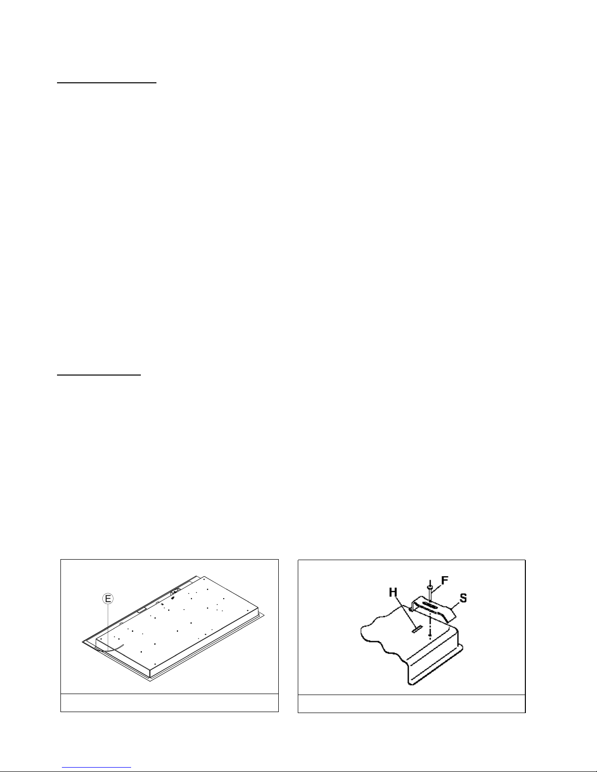
- Overturn the cooktop and correctly position seal “E” (fig. 3) under the edge of the cooktop itself, so that the
outer side of the seal perfectly matches the outer perimetral edge of the cooktop. The ends of the strips
must fit together without overlapping.
- Evenly and securely fix the seal to the cooktop, pressing into place with the fingers and remove the strip of
protective transparent from the seal and set the plate into the hole made in the cabinet.
- Fix the hob with the proper brackets “S” and fit the prominent part into the porthole “H” on the bottom; turn the
screw “F” until the bracket “S” stick on the top (fig. 4). n fastening the brackets, do not use a mechanical or
electric screwdriver. nstead, use a hand-operated screwdriver and exert only moderate force.
The adjacent walls (left, right or behind) that exceed the cooktop in height must be at a minimum distance from
the cut hole as indicated in Fig. 1 and the chart on the preceding page.
n order to avoid accidentally touching the hot cooktop bottom, it is necessary to put a horizontal wooden insert, attached
by screws, at a minimum distance of 6" below the lower surface of the cooktop (see Fig. 1).
Room Ventilation
To ensure proper operation of the appliance, be sure that the room where it is installed has adequate
ventilation.
FIG. 4
FIG. 3

7
Gas Connection
Natural Gas and Propane Gas
Natural gas installations require the connection of a gas regulator to the cooktop. You will find this
regulator among the accessories supplied with the appliance.
Assemble the regulator (noting the direction of gas flow) and transition pieces (supplied) in accordance
with the figure below.
The transition piece on the supply side of the regulator must be provided by the installer. Unions
compatible with the hose fittings must be used and connections tested for gas leaks.
Be sure that the supply connection point is accessible with the appliance installed.
WARNING:
Be sure the hose assembly is restrained from accidental contact with the flue or flue outlet of an under-
counter oven.
Electrical Connection
The e ectrica connections of the app iance must be carried out in comp iance with oca standards and
provisions.
Before connecting the appliance, check that:
1. The electrical capacity of the main electrical supply and current sockets suit the maximum power
rating of the appliance. (See the data label attached to the bottom of the cooktop.)
2. The socket or system has an efficient ground connection in compliance with local standards and
provisions. The manufacturer is not responsible for failure to comply with these provisions.

8
Electrical Connection
The electrical connections of the appliance must be carried out in compliance with
local standards and provisions.
Before connecting the appliance, check that:
1. The electrical capacity of the main electrical supply and current sockets suit the
maximum power rating of the appliance. (See the data label attached to the bottom
of the cooktop.)
2. The socket or system has an efficient ground connection in compliance with local
standards and provisions. The manufacturer is not responsible for failure to comply
with these provisions.
hen the appliance is connected to electrical power by a socket:
• Fit a standard plug suited to the load indicated on the data label to the cable.
• Fit the wires following Fig. 5, noting the following correspondences:
Letter L (live) = wire
Letter N (neutral) = wire
Ground symbol = green or yellow-green wire
• Never use adapters or shunts for connection since these could create false
contacts and lead to dangerous overheating.
•The outlet must be accessible after the cooktop is built in.
hen the appliance is connected directly to the electrical main:
• nstall an omnipolar circuit-breaker between the appliance and the electrical main.
This circuit-breaker should be sized in compliance with local installation
regulations.
• Remember that the ground wire must not be interrupted by the circuit-breaker.
• For optimum safety, the electrical connection may also be protected by a high-
sensitivity differential circuit-breaker.
You are strongly advised to fix the yellow-green ground wire to an efficient
grounding system
FIG. 5

9
ADJUSTMENTS
Always disconnect the appliance from the electrical power source before making any
adjustments. All seals must be replaced by the technician when any adjustments are completed.
Taps
"Reduced rate" adjustment:
1.Switch on the burner and turn the relative knob to the “Reduced rate” position (small flame fig. 8 page
10).
2. Remove knob “M” (fig. 6 and 6/A) of the tap, which is simply pressed on to its rod.
3. The by-pass for minimal rate regulation can be: beside the tap (fig. 6) or inside the shaft. n any case,
to access to regulation, it can be done trought the insertion of a small screwdriver ‘’D’’ beside the tap (fig.
6) or in the hole ‘’C’’ inside the shaft of the tap (fig 6/A).
Turn the throttle screw to the right or left until the burner flame has been adequately regulated to the
“Reduced rate” position.
The flame should not be too low: the lowest small flame should be continuous and steady. Re-assemble
the several components.
It is understood that only burners operating with Natural Gas or City Gas should be subjected to
the above-mentioned adjustments. The screw must be fully locked when the burners operate with
Propane (turn clockwise).
The operations described above can be carried out easily, whatever the position of the cooktop or
however it is fastened to the work surface.
THE BURNERS DO NOT REQUIRE ANY REGULATION OF INCO ING AIR.
FIG. 6 FIG. 6/A

10
Replacing Nozzles
The burners can be adapted to suit different types of gas by fitting the nozzles that correspond to the gas
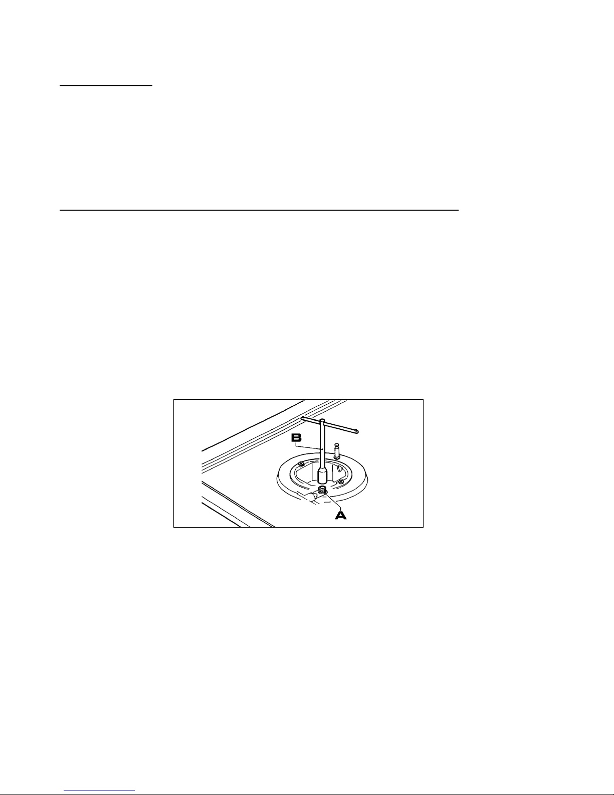
used. To do this, it is necessary to remove the burner heads and use a straight key "B", to unscrew the
nozzle "A" (see Fig. 7) and replace it with a nozzle corresponding to the gas used.
Be sure the nozzle is seated tightly.
After making these replacements, the technician must regulate the burners as described in
Adjustments on the previous page and apply the label corresponding to the new gas type in place
of that previously applied. This label is contained in the spare nozzle bag.
How to change the setting of the pressure regulator supplied with the cooktop:
The gas regulator was set up to Natural Gas. To convert to LP Gas:
1. Unscrew the aluminum cap
2. Remove and turn the plastic pin 180°
3. Screw in the plastic pin
4. Screw in the aluminum cap
For ease of the fitter, we have prepared a table indicating the flow capacities, the heat capacities of the
burners, the diameter of the nozzles and the working pressure for the various types of gas.
CONVERS ONS
FIG. 7
Tabla de contenidos
Otros manuales de Quemador de Summit