STREIVOR DemandAire Bronze Manual de usuario

Striving for Excellence
Photo to Come
DemandAire Bronze
Kitchen Ventilation Control System
www.streivor.com
Installation and Operations Manual

2
Streivor DemandAire Bronze Control Panel Installation and Operations Manual
2150 Kitty Hawk Road, Livermore, CA 94551 | (925) 960-9090 | Fax: (925) 960-9055
General Information
Acronyms ................................................................................................................................................................................3
Pre-Installation Precautions ....................................................................................................................................................4
DemandAire Control Panel Drawing Sample ..........................................................................................................................4
DemandAire Control Panel: Hood Mounted ...........................................................................................................................5
DemandAire Control Panel: Wall Mounted .............................................................................................................................5
Installation Procedures
Control Circuit Input Power Wiring..........................................................................................................................................6
Motor Circuit Input Power Wiring (Motor Starters Provided by Streivor) ................................................................................6
Motor Circuit Output Power Wiring (Motor Starters Provided by Streivor) .............................................................................7
Overload Setting (Motor Starters Provided by Streivor)..........................................................................................................7
Recommended Overload Setting for Single-Phase Motors....................................................................................................8
Recommended Overload Setting for Three-Phase Motors.....................................................................................................8
Fan Control Signal Wiring (Motor Starters Not Provided by Streivor) .....................................................................................8
Light Power Circuit Wiring.......................................................................................................................................................9
Internal Hood Fan (IHF) Power Circuit Wiring for SmartAire Technology Hoods ....................................................................9
Fire Suppression System (FSS) Switch Circuit Wiring ..........................................................................................................10
Ambient Resistance Temperature Detector (ARTD) Wiring ...................................................................................................11
Hood Canopy and/or Duct Collar Temperature Monitor Wiring ............................................................................................12
Optional: Shunt Trip Breaker Wiring......................................................................................................................................13
Optional: Modbus TCP Communication Wiring ....................................................................................................................13
Electric Gas Valve Input Power Wiring ..................................................................................................................................14
Electric Gas Valve Output Power Wiring ...............................................................................................................................14
Operation Procedures
Start Up .................................................................................................................................................................................15
Human Machine Interface (HMI) Touch Screen Control........................................................................................................15
Home Screen.........................................................................................................................................................................15
Customer Service Screen......................................................................................................................................................16
System Information Screen ..................................................................................................................................................16
Temperature Status Screen...................................................................................................................................................16
Fan Motor Status Screens.....................................................................................................................................................16
Secure Settings .....................................................................................................................................................................17
Temperature Dierential Settings Screen (Management) ......................................................................................................17
Timer Settings (Management) ...............................................................................................................................................17
Fire Suppression System Settings (Management) ................................................................................................................18
USB Removal Screem...........................................................................................................................................................18
Restore Factory Settings (Management)...............................................................................................................................18
Electrical Gas Valve Reset Relay...........................................................................................................................................19
Alarms ...................................................................................................................................................................................20
Temperature Monitor Alarm...................................................................................................................................................20
High Temperature Alarm........................................................................................................................................................20
Fan Motor Overload Alarm ....................................................................................................................................................20
Fire Suppression System Alarm ............................................................................................................................................21
Warranty
Warranty Information.............................................................................................................................................................22
Table of Contents

3
Streivor DemandAire Bronze Control Panel Installation and Operations Manual
2150 Kitty Hawk Road, Livermore, CA 94551 | (925) 960-9090 | Fax: (925) 960-9055
Acronyms
ARTD Ambient Resistance Temperature Detector
BMS Building Management System
CKV Commercial Kitchen Ventilation
DCKV Demand Control Kitchen Ventilation
DCP DemandAire Control Panel
EC Electronically Commutated
ECM Exhaust Collar Mounted
FSS Fire Suppression System
HCM Hood Canopy Mounted
HMI Human Machine Interface
IHF Internal Hood Fan
MBD Motorized Balance Damper
MUA Make Up Air
PLC Programmable Logic Controller
RTD Resistance Temperature Detector
VFD Variable Frequency Drive
General Information

4
Streivor DemandAire Bronze Control Panel Installation and Operations Manual
2150 Kitty Hawk Road, Livermore, CA 94551 | (925) 960-9090 | Fax: (925) 960-9055
General Information
Pre-Installation Precautions
Hood, Electrical, and Rough-In Schedules Field Wiring Diagram
Equipment Layout and Electrical Conduit RoutingInstallation Details
Serial
Number
DemandAire Control Panel Drawing Sample
WARNING
PRIOR TO MAKING ANY ELECTRICAL CONNECTIONS TO THE CONTROL PANEL, READ AND
UNDERSTAND THIS ENTIRE INSTALLATION AND OPERATIONS MANUAL. ALL WORK ON THE
CONTROL PANEL SHOULD BE PERFORMED BY QUALIFIED CONTRACTORS IN ACCORDANCE WITH
ALL APPLICABLE PREVAILING CODES AND STANDARDS.
THE CONTROL PANEL HAS MULTIPLE ELECTRICAL CONNECTIONS. VERIFY THAT ALL POWER HAS
BEEN DISCONNECTED TO THE CONTROL PANEL PRIOR TO WORKING ON OR NEAR THE CONTROL
PANEL. LOCK OUT / TAG OUT ALL OF THE DISCONNECT SWITCHES OR CIRCUIT BREAKERS TO
PREVENT ACCIDENTAL POWER UP.
ALL ELECTRICAL WIRING AND CONNECTIONS TO THE CONTROL PANEL SHALL BE IN ACCORDANCE
WITH THE PREVAILING CODES, THE NATIONAL ELECTRICAL CODES, AND ANSI/NFPA70.
VERIFY THAT THE SERIAL NUMBER ON THE WIRING DIAGRAM (SEE SAMPLE DRAWING) PROVIDED
WITH THE CONTROL PANEL MATCHES THE SERIAL NUMBER OF THE CONTROL PANEL BEFORE
USING THE WIRING DIAGRAM FOR REFERENCE.
VERIFY THAT THE VOLTAGE AND WIRE AMPERAGE CAPACITY AND WIRE INSULATION IS IN
ACCORDANCE WITH THE CONTROL PANEL NAMEPLATE.
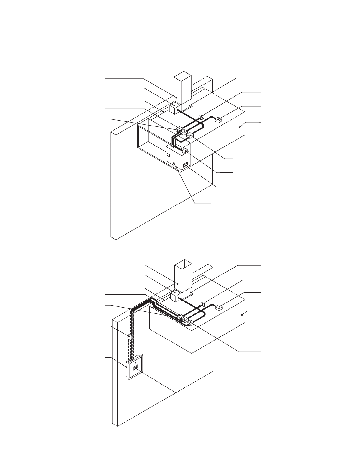
5
Streivor DemandAire Bronze Control Panel Installation and Operations Manual
2150 Kitty Hawk Road, Livermore, CA 94551 | (925) 960-9090 | Fax: (925) 960-9055
Wall Mounted DemandAire
Control Panel (Recessed)
Hood Duct Collar Access Enclosure
with Temperature Monitor Hood Light Fixture J-Box
Hood Light Fixture J-Box
SmartAire Internal Hood
Fan J-Box (optional)
SmartAire Internal Hood
Fan J-Box (optional)
Temperature Monitor J-Box (optional)
Temperature Monitor J-Box
(Optional)
Hood Light Power J-Box
Hood Light Power J-Box
SmartAire Internal Hood Fan
Power J-Box (optional)
SmartAire Internal Hood Fan
Power J-Box (optional)
Remote Ambient
Temperature Monitor
General Information
Exhaust Duct
Exhaust Duct
Rear Stando
Rear Stando
Hood Canopy
Hood Canopy
Hood Duct Collar
Hood Duct Collar
DemandAire Control Panel: Hood Mounted
DemandAire Control Panel: Wall Mounted
Cabinet Mounted Human Machine
Interface
Cabinet Mounted Ambient Temperature
Monitor
Hood Duct Collar Access Enclosure
with Temperature Monitor
Cabinet Mounted DemandAire Control
Panel
Control Panel Mounted
Human Machine Interface

6
Streivor DemandAire Bronze Control Panel Installation and Operations Manual
2150 Kitty Hawk Road, Livermore, CA 94551 | (925) 960-9090 | Fax: (925) 960-9055
Control Circuit Input Power Wiring
a. Verify that all supply power to the control panel is locked out and tagged out.
b. Verify that the circuit breaker amperage is sized correctly for the control circuit per the DemandAire Control Panel
(DCP) drawings.
c. Connect 120 VAC single phase power to the terminal blocks in the control panel labeled H, N, and Ground (Figure 1).
d. The wires should be torqued to 0.6-0.8 N•m at the terminal blocks.
Motor Circuit Input Power Wiring (Motor Starters Provided by Streivor)
a. Verify that all power to the control panel is locked out and tagged out.
b. Verify that the circuit breaker amperage is sized correctly for each motor input power circuit.
c. Verify that the voltage and phase of each motor circuit is correct per the DCP drawings.
d. Connect input power to the input power terminal blocks as shown on the DCP drawings (Figure 2).
e. The wires should be torqued to 1.5-1.8 N•m at the terminal blocks.
FIGURE 1: Control Circuit Input Power
Installation Procedures
FIGURE 2: Motor Circuit Input Power

7
Streivor DemandAire Bronze Control Panel Installation and Operations Manual
2150 Kitty Hawk Road, Livermore, CA 94551 | (925) 960-9090 | Fax: (925) 960-9055
FIGURE 4: Motor Starter (If Provided by Streivor)
Overload Setting (Motor Starters Provided by Streivor)
a. Verify that all power to the control panel is
locked out and tagged out
.
b. Each overload should have been set by the factory to the recommended setting per the table(s) below.
c. Verify that each overload has been set to 125% of the full load amps displayed on the corresponding motor nameplate.
d. The overload setting can be adjusted as needed by rotating the dial to the desired amperage value (Figure 4).
Overload
Setting Dial
FIGURE 3: Motor Circuit Output Power
Motor Circuit Output Power Wiring (Motor Starters Provided by Streivor)
a. Verify that all power to the control panel is
locked out and tagged out
.
b. The output terminals located on the Motor Starter(s) have been pre-wired to the designated output power
terminal
blocks
in the control panel. Connect the output power
terminal blocks
to the designated fan motor(s) as shown on
the DCP drawings (Figure 3).
c. The wires should be torqued to 1.5-1.8 N•m at the
terminal blocks
.
Installation Procedures

8
Streivor DemandAire Bronze Control Panel Installation and Operations Manual
2150 Kitty Hawk Road, Livermore, CA 94551 | (925) 960-9090 | Fax: (925) 960-9055
HP 115V 208V 230V
1/6 5.5 3.0 2.8
1/4 7.3 4.0 3.7
1/3 9.0 5.0 4.5
1/2 12.3 6.8 6.1
3/4 17.3 9.5 8.6
1 20.0 11.0 10.0
HP 208V 230V 460V
1/2 3.0 2.8 1.4
3/4 4.4 4.0 2.0
1 5.8 5.3 2.6
1 1/2 8.3 7.5 3.8
2 9.4 8.5 4.3
3 13.3 12.0 6.0
5 20.9 19.0 9.5
7 1/2 30.3 27.5 13.8
10 38.5 35.0 17.5
15 57.8 52.5 26.3
Recommended Motor Overload Settings for Single-Phase Motors
Recommended Motor Overload Settings for Three-Phase Motors
Installation Procedures
Fan Control Signal Wiring (Motor Starters Not Provided by Streivor)
a. Connect the terminal blocks in the control panel designated for the start/stop fan control signals to the appropriate
external destination — Motor Starter(s) (by others) or Building Management System (BMS) (Figure 5).
b. Refer to the DCP drawings for more information on the control signals available (24 VDC, 120 VAC, or Dry Contact).
c. The wires should be torqued to 0.6-0.8 N•m at the terminal blocks.
FIGURE 5: Fan Control Signal Wiring (if Motor Starters Not Provided by Streivor)

9
Streivor DemandAire Bronze Control Panel Installation and Operations Manual
2150 Kitty Hawk Road, Livermore, CA 94551 | (925) 960-9090 | Fax: (925) 960-9055
Installation Procedures
Light Power Circuit Wiring
a. Verify that all power to the control panel is
locked out and tagged out
.
b. Connect 120 VAC single phase power from terminal block 11 (hot), terminal block 12 (neutral), and ground in the
control panel to the wires labeled “Lights” in the junction box on the hood (Figure 6).
c. The wires should be torqued to 0.6-0.8 N•m at the terminal blocks.
FIGURE 6: Light Power Circuit Wiring
Internal Hood Fan (IHF) Power Circuit Wiring for SmartAire Technology Hoods
Per NFPA 96 Section 8.3.2: When its re-extinguishing system discharges, makeup air supplied internally to a
hood shall be shut o.
a. Verify that all power to the control panel is locked out and tagged out.
b.Connect 120 VAC single phase power from terminal block 3(hot), terminal block 4(neutral), and ground in the
control panel to the wires labeled “IHF” in the junction box on each hood (Figure 7).
c. Internal Hood Fan power to terminal blocks 3and 4 will be automatically shunt during a re suppression system
activation to comply with NFPA 96 Section 8.3.2.
d.The wires should be torqued to 0.6-0.8 N•m at the terminal blocks.
FIGURE 7: Internal Hood Fan Power Circuit Wiring

10
Streivor DemandAire Bronze Control Panel Installation and Operations Manual
2150 Kitty Hawk Road, Livermore, CA 94551 | (925) 960-9090 | Fax: (925) 960-9055
FIGURE 8A: Fire Suppression System (FSS) Switch Circuits
Installation Procedures
Terminal Blocks
Allocated for:
Shunt Trip
Building Alarm
{
{
FIGURE 8B: FSS Switch for Building Alarm Circuit
Note: Use FSS
Switch with Lugs
for Building Alarm
Circuit
Fire Suppression System (FSS) Switch Circuit Wiring
a. Verify that all power to the control panel is locked out and tagged out.
b. Locate the FSS switch in the FSS control panel. The FSS switch (also referred to as microswitch) shall have one set
of single-pole-double-throw contacts (Figure 8A).
c. Connect the terminal blocks in the control panel to the FSS Switch(es) (Figure 8A). The building alarm circuit must
be connected to the switch with lugs (Figure 8B).
d. Connect the building alarm circuit to the terminal blocks designated for the building alarm in the DCP (Figure 8A).
e. Refer to the DCP drawings for more detail regarding wiring additional FSS switches.
f. The wires should be torqued to 0.6-0.8 N•m at the terminal blocks.
Tabla de contenidos


