Stream NXT Manual de usuario

Stream NXT
-
assembly instructions
Recommended settings
CG (measured from root leading edge):
Speed/launch camber (+down, near the wing root):
Cruise camber (+down, near the wing root):
Thermal camber (+down, near the wing root):
Aileron deflections (+down, -up):
Elevator deflections (+down, -up):
Rudder deflections (+left, -right):
65-70mm
0mm
+2mm
+5...+8mm
+12/-12mm
+9/-9mm
+15/-15mm
Kit contents: wing, fuselage, tail feathers, small parts.
Small parts supplied with the kit.
Servo locations have the skin indented for covers. Your kit may have
the servo wells already made at the factory. If so, you can skip a few
steps.
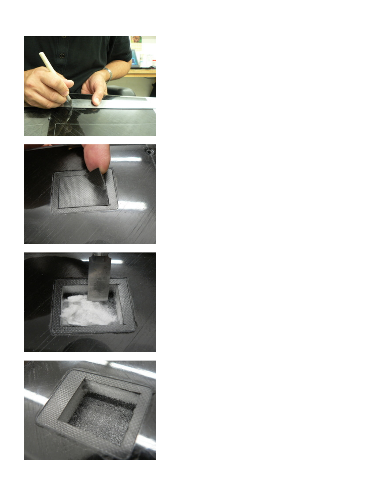
Start by cutting out the skin inside the servo locations.
Peel off the skin carefully. The cuts should be at least 3mm inside
the outline. More if your servo is smaller and you want to reduce the
size of the servo pocket.
Pick out the foam inside the servo pockets carefully, first with a
regular X-acto knife, then using a spade knife when near the top
skin.
Clean the foam out completely, carefully scraping it off the top skin
with the spade knife. You need as much depth for the servos as
possible. You should see the wire channels in the corners of the
pockets now.

If your servos have mounting lugs, you may want to remove them,
depending on how you plan to attach the servos inside the pockets.
Prepare the aileron control horns by re-drilling the hole with a
sharpened piece of the 1.5mm pushrod wire supplied with the kit. If
desired, you can use a smaller size wire for aileron pushrods (easier
to bend); 1.2mm wire is sufficiently strong for the job, but 1.5mm is
stiffer (stiffness helps to reduce your chances of aileron flutter).
Use masking tape, and mark the locations of the cuts for the aileron
pushrod exits and the control horns. The exit slots must be located
near the outside edge of the servo pockets. Measure the distance on
the bottom of the wings, then transfer the mark to the top. The
control horns must be slightly offset to the outside, to allow for the
pushrod wire bend radius.
Carefully cut the skin along the marked lines. The exit slots must be
about 20mm long.

When the skin is cut, pick the foam out of the slots using an X-acto
knife and/or the tip of a needle file.
The vertical wall must be removed completely on the aileron side
and about 1/2 way down on the wing side.
Use a sharpened wire to make a guide hole for the pushrod channel.
The wire ideally must exit near the outer edge of the servo pocket,
close to the bottom skin.

Use a rectangular needle file to make the pushrod channel by
expanding the guide hole. The channel must be elongated vertically
to provide space for the pushrod travel up+down during the aileron
deflections.
The needle file inside the servo pocket. You can reverse the direction
and expand the channel from the pocket side also.
Trial fit the control horn in the slot. Do not glue at this time.
Sharpen slightly the end of one pushrod wire. Then make a sharp
bend about 3mm from the end.

Tape the aileron ends to the wing root tabs to keep them at zero
deflection. Insert the long end of the pushrod wire into the channel.
Install the control horn into the slot and temporarily tape it down.
Prepare the servos and servo arms. Set the servos to the neutral
position. Attach two servo arms as close to 90 degrees as possible.
Draw a line on each arm at exactly 90 degrees. Mark locations of the
new holes, about 4.5-5.0 mm from the axis.
Drill new holes in the servo arms. Cut off all excess material around
the holes to make two nice looking very short servo arms. The
objective is to hide the entire servo and its arm under the cover.
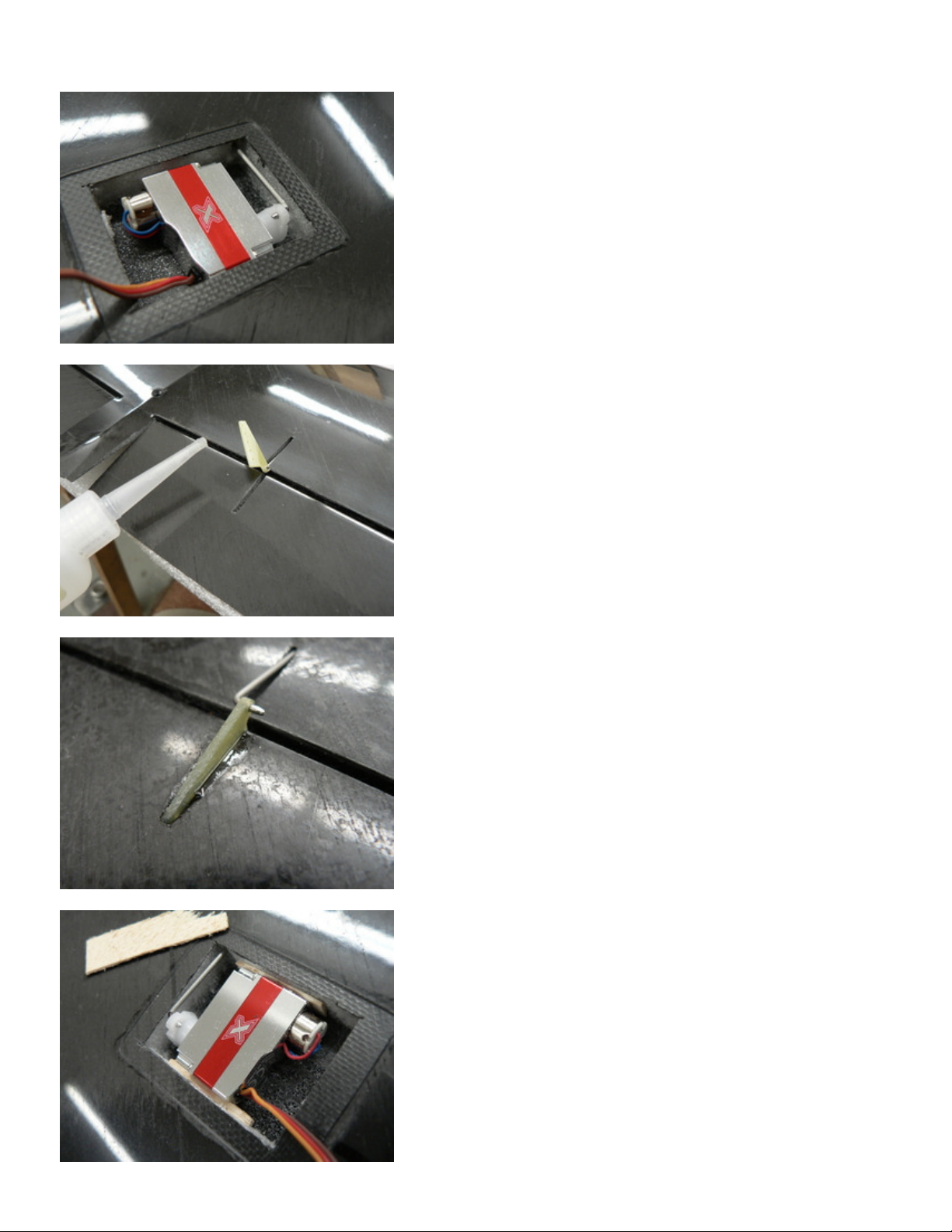
Important! Electronically deflect both servos equally about 20-25
degrees towards the leading edge. This will be the neutral point for
the ailerons. This will provide more down travel for the ailerons
(when used for landing). Drop the servos into the pockets and center
them between the fore/aft walls of the pockets. Mark the location of
the bend on the pushrod wire.

Remove the pushrod wire and the control horn from the wing. Cut
the wire about 3 mm past the mark. Sharpen the end of the wire
slightly. It is much easier to do this BEFORE bending the end.
Bend the pushrod end at the mark.
Insert the pushrod into the servo arm. Verify that the servo and
control horn are square to each other, otherwise the servo will be
forced to angle slightly when inside the pocket. Correct the pushrod
if needed.
Insert the aft end of the pushrod through the channel carefully. The 3
mm bend should fit inside the vertically elongated channel. Install
the control horn into the slot again temporarily.
Drop the servo into the pocket again. Insert the pushrod into the arm.
Verify that the servo is sitting flat and has some space at both
fore/aft walls of the pocket. Temporarily tape the servos into the
pocket to prevent them falling out during the next step.
Lift the control horn off the slot. Apply medium CA or epoxy into
the slot.
Install the control horn permanently now. Remove excess glue if
needed. Try to avoid getting glue onto the hinge line!
Important! Keep the servo arms in their exact offset position by
plugging the servos into the receiver with a battery, and keep the
ailerons taped to the wing roots. Make balsa shims that will go on
both sides of the servo and wedge the servo inside the pocket
slightly. Do not use excessive force or the top wing skin will warp at
the pocket and you will have a visible bad spot there, both visually
and aerodynamically.

Apply some 5-min epoxy and microballoons mix to the corners
between the servo and the pocket walls. Try to avoid getting epoxy
onto the top skin, or it may warp the top skin when epoxy shrinks a
little. Also, removing servos (if needed for repair) will be
problematic.
A connector for the wing is optional, but it helps greatly if you are
planning to disassemble the model for transportation frequently as
most people do. A simple option for the wing connector is to use a 4
pin section of a circuit board pin strip. Mark the location of the servo
wire channel and the connector on a piece of a masking tape. The
recommended position for the connector is near the side of the
fuselage, to leave the space in the middle for ballast and control
lines.
The line shows the approximate location of the wire channels and is
drawn by connecting the corners of the servo pockets, where the
wire channels are visible. The connector slot must be located on or
near the wire channel. Make a slot in the wing for one part of the
connector. Verify that the servo wire channels open up into the slot
and are clear of glue.
Transfer the location onto the fuselage.

Make a rectangular hole in the fuselage. Allow for some freedom of
movement around the connector. The two connector parts must mate
exactly and the fuselage part will be exactly positioned by the wing
in a later step.
Solder the male connector part to the servo wires (after the servo
installation is done).
Prepare the wire harness that will go inside the fuselage.
Glue the wing part of the connector inside the wing, either flush or
slightly below the wing surface. Use the mating part of the connector
for keeping the pins vertically. After the epoxy cures, clean the
excess epoxy around the base of the connector.


