Stamina wirk Linea Manual de usuario

When calling for parts or
service, please specify
the following number :
Model#: 85-4000
Owner's
Manual
This Product is Distributed Exclusively by
2040 N. Alliance, Springeld, MO 65803
Customer Service
1 (800) 375-7520
www.staminaproducts.com
Product May Vary Slightly From Pictured.
STAMINA PRODUCTS
MADE IN CHINA
© 2014 Stamina Products, Inc.
2014, 11
TM

2
To help you get started, we have pre-assembled most of your
WirkTM Linea Standup Workstation at the factory with the exception
of those few parts left unassembled for shipping purposes.
Simply follow the few assembly instructions set forth in this manual.
Should you have any questions,
please call our Customer Service Department toll-free number,
1 (800) 375-7520
Monday - Thursday, 7:30 A.M. - 5:00 P.M., Central Time.
Friday, 8:00 A.M. - 3:00 P.M., Central Time.
TELEPHONE
CUSTOMER SERVICE
Tel: 1 (800) 375-7520
FAX
CUSTOMER SERVICE
Fax: (417) 889-8064
MAIL
STAMINA PRODUCTS, INC.
ATTN: Customer Service
P.O. Box 1071
Springeld, MO. 65801-1071
ONLINE
CUSTOMER SERVICE
www.staminaproducts.com
To enact your warranty, please register your product
by going to register.staminaproducts.com
Call Us First
www.staminaproducts.com
1(800)
375-7520
Customer Service
THANK YOU FOR PURCHASING THE
WirkTM Linea Standup Workstation
TABLE OF CONTENTS
Hardware Identication Chart .................... 3
Assembly Instructions ................................ 4
Operational Instructions ............................. 9
Storage ....................................................... 10
Maintenance ............................................... 10
Warranty ..................................................... 11
Product Parts Drawing .............................. 12
Parts List .................................................... 13
WirkTM Coaster Toss Rules ....................... 14
Fax/Mail Ordering Form ............................ 15

37 Bolt, Button Head (M8 x 1.25 x 20mm) 3
40 Bolt, Button Head (M6 x 1 x 15mm) 8
44 Washer (M8) 6
45 Nylock Nut (M8 x 1.25) 5
Part Number and Description Qty
33 Bolt, Button Head (M8 x 1.25 x 110mm) 2
34 Bolt, Button Head (M8 x 1.25 x 60mm) 1
35 Bolt, Button Head (M8 x 1.25 x 50mm) 2
41 Carriage Bolt (M8 x 1.25 x 50mm) 1
3
length
length
mm.
in.
INCHES
This chart is provided to help identify the fasteners used in the assembly process. Place the washers or
the ends of the bolts or screws on the circles to check for the correct diameter. Use the small scale to
check the length of the bolts and screws.
NOTICE: The length of all bolts and screws, except those with flat
heads, is measured from below the head to the end of the bolt
or screw. Flat head bolts and screws are measured from the
top of the head to the end of the bolt or screw.
After unpacking the unit, open the hardware bag and make sure that you have all the following
fasteners. Some fasteners may be already attached to the parts.
MILLIMETERS
0 10 20 30 40 50 60 70 80 90 100 110 120 130 140 150
0 1/2 1 1/2 2 1/2 3 1/2 4 1/2 5 1/2 6
6 8 10 12
3/16" 1/4" 5/16" 3/8" 1/2"
HARDWARE IDENTIFICATION CHART

ASSEMBLY INSTRUCTIONS
STEP 1
Attach the UPRIGHT(2) to the BASE FRAME(1) with BUTTON HEAD BOLTS(M8x1.25x20mm)(37).
4
Place all parts from the box in a cleared area and position them on the oor in front of you. Remove
all packing materials from your area and place them back into the box. Do not dispose of the packing
materials until assembly is completed. Read each step carefully before beginning. If you are missing
a part, please go to staminaproducts.com under the Service section and order the part needed,
U.S.). Our Customer Service Staff is available to assist you from 7:30 A.M. to 5:00 P.M. (Central
Time) Monday through Thursday and 8:00 A.M. to 3:00 P.M. (Central Time) on Friday.
1
2
37
37
16

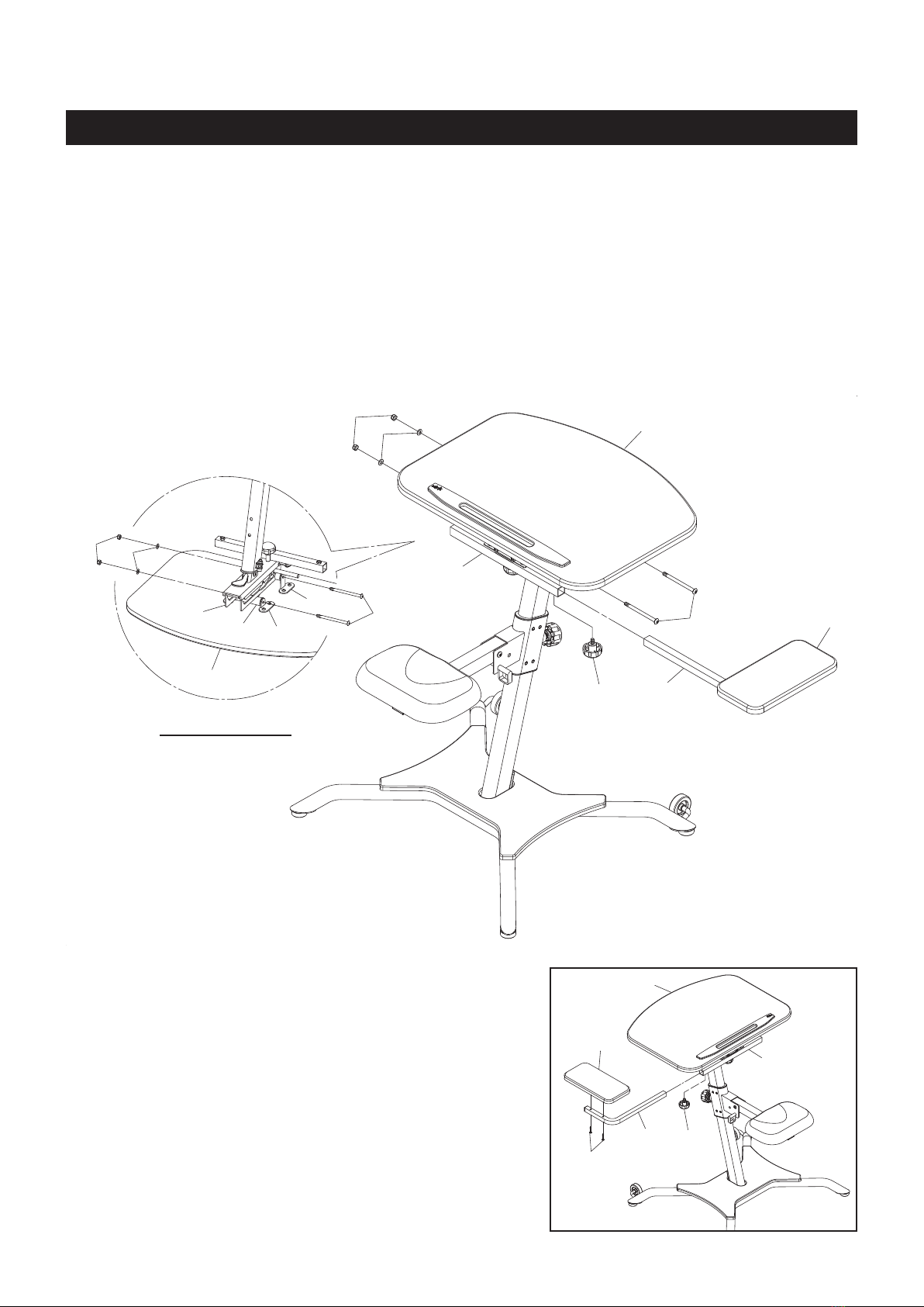
ASSEMBLY INSTRUCTIONS
STEP 2
Slide the TABLE SLIDER(6) onto the TABLE POST(3). Insert the CARRIAGE BOLT(M8x1.25x50mm)
(41) through the square hole on the TABLE POST(3) and the slot on the TABLE SLIDER(6).
STEP 3
Attach the SIDE TABLE SUPPORT(7) to the TABLE POST(3) by sliding the SIDE TABLE SUPPORT(7)
onto the CARRIAGE BOLT(M8x1.25x50mm)(41), then insert the bolts which are welded on the SIDE
TABLE SUPPORT(7) through the holes on the TABLE POST(3) and secure with WASHERS(M8)(44)
and NYLOCK NUTS(M8x1.25)(45).
STEP 4
Attach the ADJUSTMENT KNOB(24) and WASHER(M8)(44) to the CARRIAGE BOLT(M8x1.25x50mm)
(41) to lock the TABLE SLIDER(6) in position.
5
3
6
41
44
45
44
45
24
44
7

ASSEMBLY INSTRUCTIONS
STEP 5
Refer illustrations A, B, and C. Place the BACK SUPPORT(9) into the TABLE SLIDER(6) and turn it as
shown in the below illustrations to install the BACK SUPPORT(9) into position.
STEP 6
Attach the SEAT SUPPORT(5) to the SEAT SLIDER(4) with BUTTON HEAD BOLT(M8x1.25x60mm)(34),
WASHER(M8)(44), and NYLOCK NUT(M8x1.25)(45).
STEP 7
Attach the SEAT(18) to the SEAT SUPPORT(5) with BUTTON HEAD BOLTS(M8x1.25x50mm)(35).
Insert the PULL PIN(29) into the SEAT SLIDER(4) for storage.
6
3
9
9
6
6
9
6
9
6
5
18
29
34
35
44
45 4
A.
B.
C.

ASSEMBLY INSTRUCTIONS
STEP 8
Refer to the illustration below. Attach the MOUNTING BRACKETS(10) and TALL MOUNTING
BRACKETS(11) to the bottom side of the TABLE(15) with BUTTON HEAD BOLTS(M6x1x15mm)(40).
7
11
11
10
40
15
15
40
10
40
40
BOTTOM VIEW
ASSEMBLY INSTRUCTIONS
8
STEP 9
Refer to the Bottom View below. Attach the TABLE(15) to the unit by attaching the TALL MOUNTING
BRACKETS(11) to the TABLE SLIDER(6) and attaching the MOUNTING BRACKETS(10) to the BACK
SUPPORT(9) with BUTTON HEAD BOLTS(M8x1.25x110mm)(33), WASHERS(M8)(44), and NYLOCK
NUTS(M8x1.25)(45).
STEP 10
Attach the SIDE TABLE(17) by inserting the SIDE TABLE POST(8) into the SIDE TABLE SUPPORT(7)
and secure with the LOCKING KNOB(23).
33
44
45
8
23
33
44
45
10
11
6
9
15
15
7
17
23
15
7
8
17
39
BOTTOM VIEW
NOTE:
You can attach the SIDE TABLE(17) to the left side. Remove
the BUTTON HEAD BOLTS(M6x1x30mm)(39) from the SIDE
TABLE POST(8) to disassemble the SIDE TABLE(17). Turn
the SIDE TABLE POST(8) to the left side and attach the SIDE
TABLE(17) back to the SIDE TABLE POST(8) with BUTTON
HEAD BOLTS(M6x1x30mm)(39). Inserting the SIDE TABLE
POST(8) into the SIDE TABLE SUPPORT(7) and secure with
the LOCKING KNOB(23).

SEAT ADJUSTMENT
1. The SEAT(18) can be set to a 30 degree angle from
horizontal. Set the SEAT(18) with the desired angle and
lock in position with the PULL PIN(29).
2. There are four adjustment holes on the UPRIGHT(2) for
adjusting the SEAT(18) to different heights. To adjust,
loosen and pull the SEAT ADJUSTMENT KNOB(22), then
adjust the SEAT(18) height by sliding the SEAT SLIDER(4)
to the desired position and lock in place by releasing and
tightening the SEAT ADJUSTMENT KNOB(22). The pin of
the SEAT ADJUSTMENT KNOB(22) must be inserted into
one of the adjustment holes.
OPERATIONAL INSTRUCTIONS
15 15
9
6
9
6
15 15
9
6
9
6
9
TABLE ANGLE ADJUSTMENT
Refer to the illustrations below. The angle of the TABLE(15) can be set to different angles by placing the
BACK SUPPORT(9) to a different slot on the TABLE SLIDER(6).
5
18
29
4
22
2
15
24
2
13
12
TABLE ADJUSTMENT
1. The TABLE(15) can adjust forward or backward. To
adjust, loosen the ADJUSTMENT KNOB(24). Adjust the
TABLE(15) to the desired position and lock in place by
tightening the ADJUSTMENT KNOB(24).
2. The height of the TABLE(15) is adjustable. To adjust, open
the QUICK RELEASE(13). Push the Lever (12) down to
allow the Gas Shock to raise the TABLE(15) up, or you
can push down on the TABLE(15) to lower it. Lock the
TABLE(15) at the desired position by closing the QUICK
RELEASE(13).
Zero Degree 15 Degree 30 Degree 45 Degree

1. To store the WirkTM Linea Standup Workstation, simply keep it in a clean dry place.
2. To move the WirkTM Linea Standup Workstation, lift the SEAT(18) and use the WHEELS(30) on the
BASE FRAME(1).
The safety and integrity designed into the WirkTM Linea Standup Workstation can only be maintained
when the WirkTM Linea Standup Workstation is regularly examined for damage and wear. Special
attention should be given to the following:
1. Verify that all nuts and bolts are present and properly tightened. Replace missing nuts and bolts.
Tighten loose nuts and bolts.
2. It is the sole responsibility of the user/owner to ensure that regular maintenance is performed.
3. Worn or damaged components shall be replaced immediately or the WirkTM Linea Standup
Workstation removed from service until repair is made.
4. Only Stamina Products supplied components shall be used to maintain/repair the WirkTM Linea
Standup Workstation.
5. Keep your WirkTM Linea Standup Workstation clean by wiping it off with an absorbent cloth after
use.
STORAGE
MAINTENANCE
10
OPERATIONAL INSTRUCTIONS
WEIGHT LIMITATIONS
WARNING: Serious injuries can occur from furniture tip-over. To help prevent tip-over:
Do not exceed listed weight limits
Never allow children to climb or hang on the furniture
Do not lean on the desktop in any direction
Tabla de contenidos


