3
INTRODUCTION____________________________________________________________________
This manual covers the setup and operation of the Models MIL PAC 300B and MIL PAC 310B Relocatable Rapid Deployment
Microwave Intrusion Links and Models MIL PAC 380 and MIL PAC 385 Relocatable Rapid Deployment Microwave
Transceivers. Please refer to the individual Data Sheets and Technical Manuals for Models 300B, 310B, 380 and 385 for
additional information not covered in this manual.
These portable relocatable sensors are ideal for short-term protection of vital assets such as parked aircraft, construction sites,
freight yards or anywhere the perimeter may be moved or changed.
EQUIPMENT SUPPLIED______________________________________________________________
Each MIL PAC 300B consists of one Model 300BT Transmitter, one Model 300BR Receiver, one MP01 Monitor Pac with
mating connector, charging transformer and cable, one BP01 Battery Pac with mating connector, charging transformer and
cable, two MT10 Tripods, two interconnect cables, one RF radio alarm transmitter with two foot whip antenna and two fitted
carrying cases.
Each MIL PAC 310B consists of one Model 310BT Transmitter, one Model 310BR Receiver, one MP01 Monitor Pac with
mating connector, charging transformer and cable, one BP01 Battery Pac with mating connector, charging transformer and
cable, two MT10 Tripods, two interconnect cables, one RF radio alarm transmitter with two foot whip antenna and two fitted
carrying cases.
Each MIL PAC 380 consists of one Model 380 Transceiver, one MP01 Monitor Pac with mating connector, charging
transformer and cable, one MT10 Tripod, one interconnect cable, one RF radio alarm transmitter with two foot whip antenna
and fitted carrying case.
Each MIL PAC 385 consists of one Model 385 Transceiver, one MP01 Monitor Pac with mating connector, charging
transformer and cable, one MT10 Tripod, one interconnect cable, one RF radio alarm transmitter with two foot whip antenna
and fitted carrying case.
Reference Figures 1-8 for supplied equipment.
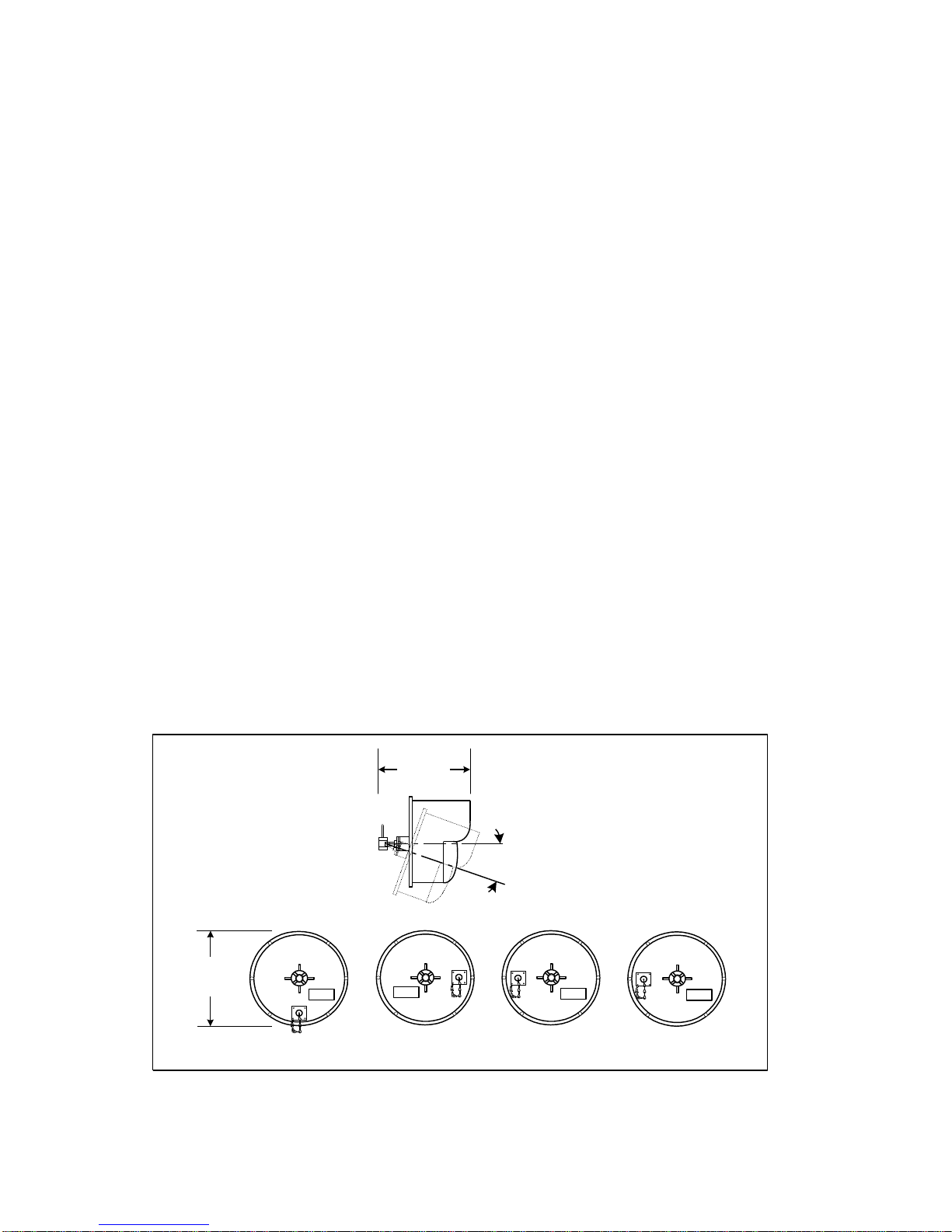
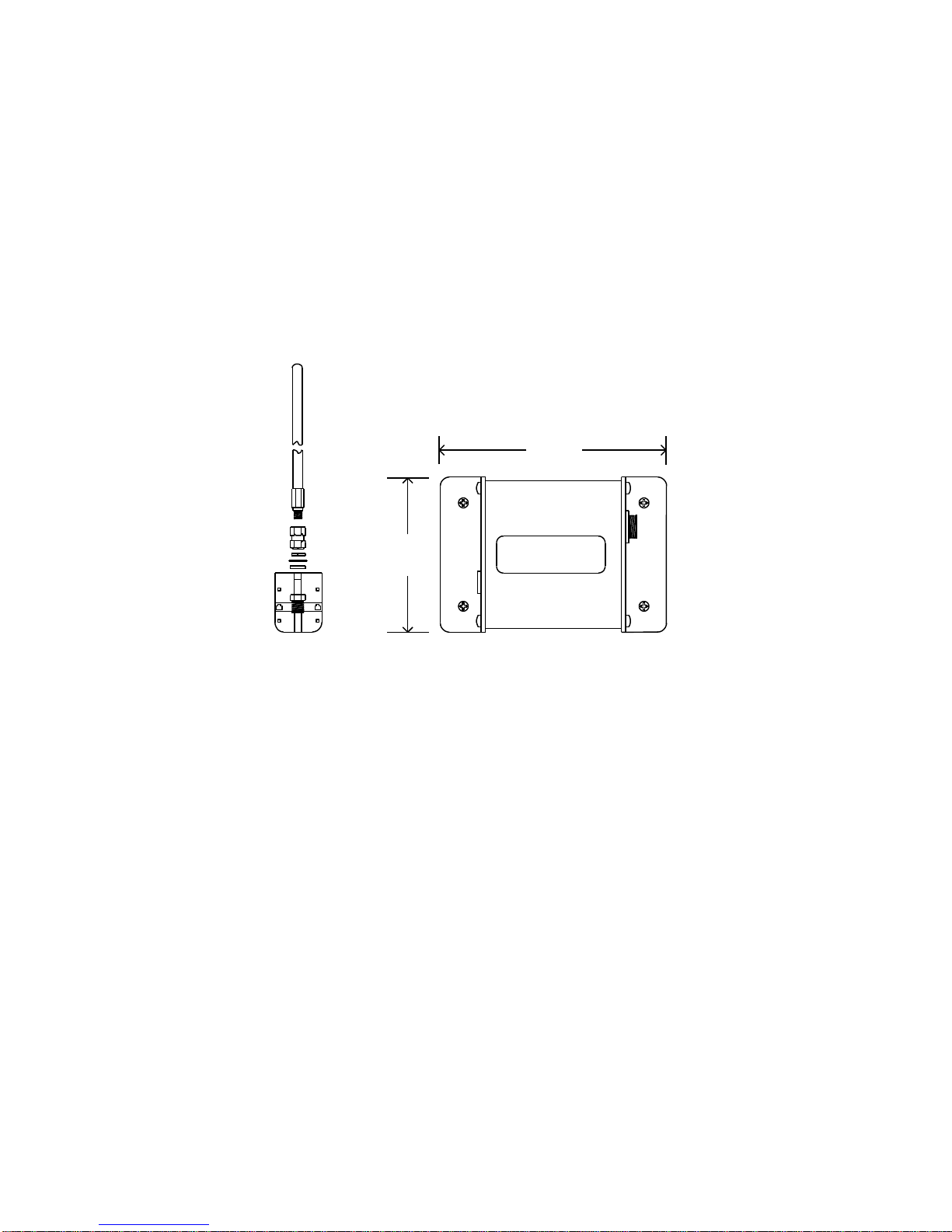
Figure 1 shows a side view of the various sensors with the tilt and swivel limits of the swivel assembly plus the MS connector
location where the interconnect cable attach from the MP01 or BP01 to the sensor.
Figure 1 – MS Connector Locations
20
o
MAX TILT
ANY DIRECTION
10.6 in.
(27cm)
Dia.
10.125 in.
(25.7cm)
380 385
300BR or 310BR300BT or 310BT