Southbend RG24-5 Manual de usuario
IMPORTANT FOR FUTURE REFERENCE
Please complete this information and retain this
manual for the life of the equipment:
Model #: __________________________
Serial #: __________________________
Date Purchased: ___________________
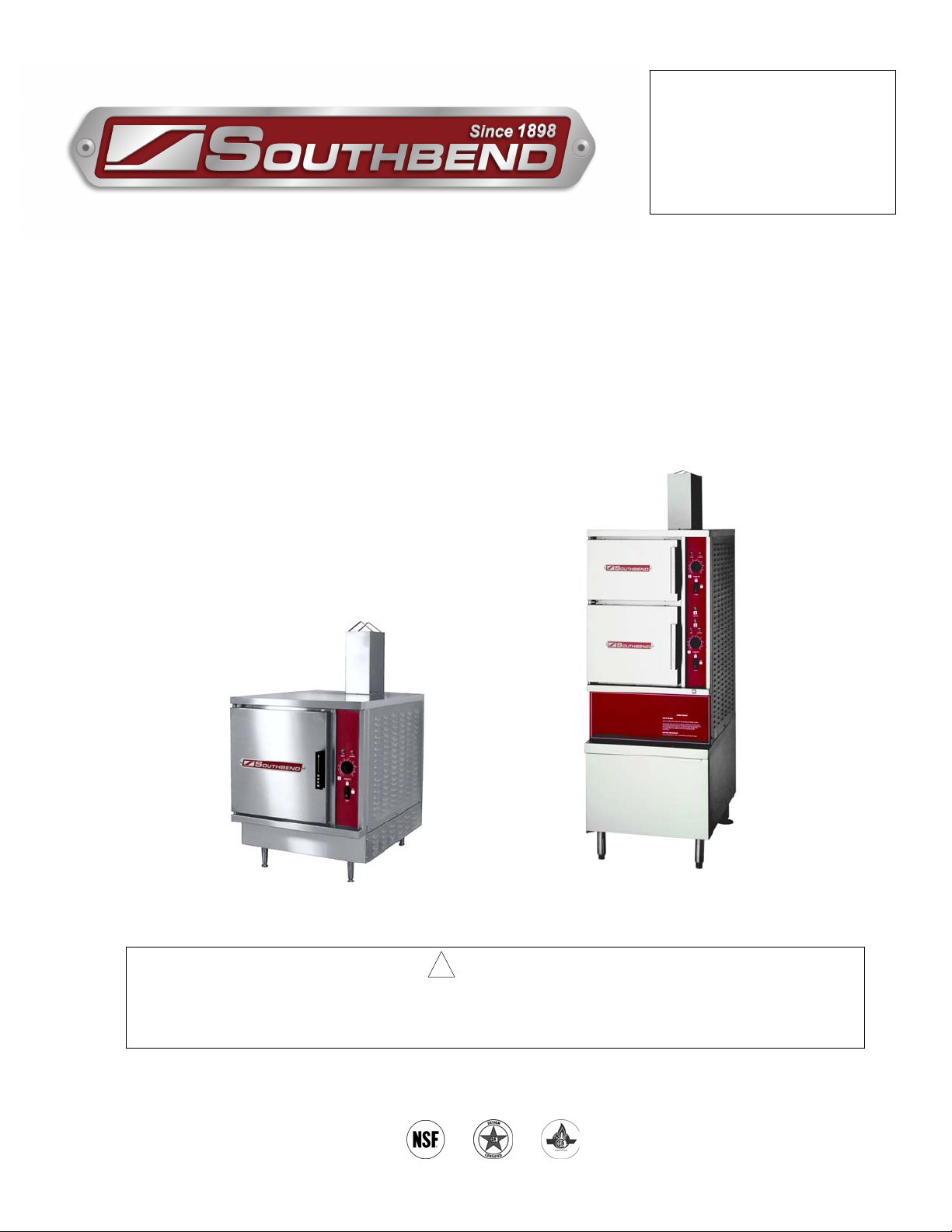
OPERATOR’S MANUAL
Gas Fired Steamers
RG24-5 SX-34GC SX-55GC
! WARNING
Improper installation, adjustment, alteration, service or maintenance can cause property damage,
injury or death. Read the installation, operating and maintenance instructions thoroughly before
installing or servicing this equipment.
1100 Old Honeycutt Road, Fuquay-Varina, NC 27526
www.southbendnc.com
MANUAL 1195732 REV0 (11/22/2011)
HEAVY DUTY STEAM
INSTALLATION AND OPERATION MANUAL, GAS FIRED STEAMER,
MODELS RG24-5, SX-34GC, SX-55GC
MANUAL 1195732 REV0 (11/22/2011) 2 HEAVY DUTY STEAM
Intended for commercial use only. Not for household use.
IMPORTANT NOTES FOR INSTALLATION AND OPERATION
This is the safety alert symbol. It is used to alert you to potential
personal injury hazards. Obey all safety messages that follow this
symbol to avoid possible injury or death.
WARNING: Improper installation, operation, adjustment, alteration,
service or maintenance can cause property damage, injury or death.
Read the installation, operating and maintenance instructions
thoroughly before installing, operating or servicing this equipment.
FOR YOUR SAFETY: Do not store or use gasoline or other
flammable vapours and liquids in the vicinity of this or any other
appliance.
PURCHASER: Instructions to be followed in the event that the
operator of this appliance smells gas must be posted in a prominent
location. This information shall be obtained by consulting the local
gas supplier.
Keep the appliance area free and clear from combustibles.
Do not obstruct the flow of combustion and ventilation air.
Adequate clearances must be maintained for servicing and proper operation.
Do not attempt to operate this unit in the event of a power failure.
This manual should be retained for future reference.

INSTALLATION AND OPERATION MANUAL, GAS FIRED STEAMER,
MODELS RG24-5, SX-34GC, SX-55GC
MANUAL 1195732 REV0 (11/22/2011) 3 HEAVY DUTY STEAM
TABLE OF CONTENTS
DESCRIPTION PAGE
1.0 Service Connections ....................................................4
2.0 Installation ............................................................7
3.0 Performance Check ....................................................12
4.0 Operation Instructions ..................................................13
SERVICE
5.0 Periodic Maintenance ..................................................17
6.0 Deliming Procedure ....................................................20
7.0 Troubleshooting ........................................................21
INSTALLATION AND OPERATION MANUAL, GAS FIRED STEAMER,
MODELS RG24-5, SX-34GC, SX-55GC
MANUAL 1195732 REV0 (11/22/2011) 4 HEAVY DUTY STEAM
1.0 SERVICE CONNECTIONS
RG24-5
INSTALLATION AND OPERATION MANUAL, GAS FIRED STEAMER,
MODELS RG24-5, SX-34GC, SX-55GC
MANUAL 1195732 REV0 (11/22/2011) 5 HEAVY DUTY STEAM
1.0 SERVICE CONNECTIONS (Continued)
INSTALLATION AND OPERATION MANUAL, GAS FIRED STEAMER,
MODELS RG24-5, SX-34GC, SX-55GC
MANUAL 1195732 REV0 (11/22/2011) 6 HEAVY DUTY STEAM
2.0 INSTALLATION
GENERAL
Installation must conform with local codes, or in the absence of local codes, with the National
Fuel Gas Code, ANSI Z223.1/NFPA 54, or the Natural Gas and Propane Installation Code,
CSA B149.1, as applicable.
1. The appliance and its individual shut off valve must be disconnected from the gas
supply piping system during any pressure testing of that system at pressures in
excess of ½ psi (3.5 kPa).
2. The appliance must be isolated from the gas supply piping system by closing its
individual manual shut off valve during any pressure testing of the gas supply
piping system at test pressures equal to or less than ½ psi (3.5 kPa).
Electrical grounding must be provided in accordance with local codes, or in the absence of local
codes, with the National Electrical Code, ANSI/NFPA 70, or the Canadian Electrical Code, CSA
C22.2, as applicable.
Ventilation must be provided in accordance with local codes, or in the absence of local codes,
with ANSI/NFPA 96 Standard for Ventilation and Fire Protection of Commercial Cooking
Operations.
WARNING: Electrical grounding instructions - units equipped with a
three-prong (grounding) plug for your protection against shock
hazard and should be plugged directly into a properly grounded
three-prong receptacle. Do not cut or remove the grounding prong
from this plug. (120 volt units only).
WIRING DIAGRAM FOR APPLIANCE IS LOCATED ON RIGHT HAND SIDE PANEL OF THE
COOKER CABINET.
NOTICE: If this equipment is being installed at over 2,000 feet altitude and was not so
specified on order, contact service department. Failure to install with proper orifice
sizing may void the warranty.
INSTALLATION AND OPERATION MANUAL, GAS FIRED STEAMER,
MODELS RG24-5, SX-34GC, SX-55GC
MANUAL 1195732 REV0 (11/22/2011) 7 HEAVY DUTY STEAM
2.0 INSTALLATION (Continued)
2.1 EXHAUST FANS AND CANOPIES:
Canopies are set over ranges, ovens, kettles, etc., for ventilation purposes. It is recommended
that a canopy extend 6" past appliance and be located 6' 6" from the floor. Filters should be
installed at an angle of 45 degrees or more with the horizontal. This position prevents dripping
of grease and facilitates collecting the run-off grease in a drip pan, usually installed with the
filter. A strong exhaust fan tends to create a vacuum in the room and may interfere with burner
performance or may extinguish pilot flames. Makeup air openings approximately equal to the
fan area will relieve such vacuum. In case of unsatisfactory performance on any appliance,
check with the exhaust fan in the “OFF” position.
2.2 WALL EXHAUST FAN:
The exhaust fan should be installed at least two feet above the vent opening at the top of the
unit.
2.3 CLEARANCES:
Adequate clearance must be provided in aisle and at the side and back. Adequate clearances
for air openings into the combustion chamber must be provided, as well as for serviceability for
use on noncombustible floors. Minimum clearance from combustible and noncombustible
construction, 3 inches on left side, 8 inches on right side and 6 inches from back.
WARNING: These procedures must be followed by qualified
personnel or warranty will be voided. An open gap floor drain is
required immediately below the appliance drain.
TO INSTALL:
1. Uncrate carefully. Report any hidden freight damage to the freight company immediately.
2. Set the unit in place. Be certain to maintain the minimum clearances from combustibles
and non-combustibles.
3. Level appliance using spirit level. Should flanged adjustable feet be provided, anchor to
floor using proper anchoring devices.
4. Seal bolts and flanged feet with Silastic or other equivalent compound.
5. Be certain to leave adequate clearances for cleaning, maintenance and service.
INSTALLATION AND OPERATION MANUAL, GAS FIRED STEAMER,
MODELS RG24-5, SX-34GC, SX-55GC
MANUAL 1195732 REV0 (11/22/2011) 8 HEAVY DUTY STEAM
INSTALLATION
GAS CONNECTION:
1. The Serial and Rating Plate on the unit indicates the type of gas your unit is equipped to
burn. DO NOT connect to any other gas type.
2. A ¾" NPT line is provided at rear for the connection. Each compartment is equipped with
an internal pressure regulator which is set at 3.5" W.C. manifold pressure for natural gas
and 10" W.C. for propane gas. Use c" pipe tap on the burner manifold for checking
pressure.
An adequate gas supply is imperative. Undersized or low pressure lines will restrict the volume
of gas required for satisfactory performance. A steady supply pressure, between 6" W.C. and
14" W.C. for natural gas and between 11" W.C. and 14" W.C. for propane gas is
recommended. With all units operating simultaneously, the manifold pressure on all units
should not show any appreciable drop. Fluctuations of more that 25% on natural gas and 10%
on propane gas will create problems, affecting burner operation. Contact your gas company for
correct supply line sizes.
Purge the supply line to clean out any dust, dirt or other foreign matter before connecting the
line to the unit. Use pipe joint compound which is suitable for use with Propane on all threaded
connections. A manual gas shut off valve for each compartment is supplied with the unit.
Test pipe connections thoroughly for gas leaks.
WARNING: Never use an open flame to check for gas leaks. Check
all connections for leaks using soapy water before use.
NOTE: If applicable, the vent from the gas appliance pressure regulator shall be
installed to the outdoors in accordance with local codes or, in the absence of local
codes, with the National Fuel Gas Code, ANSI Z223.1 or the Natural Gas Installation
Code CAN/CGA-B149.1 or the propane installation code, CAN/CGA-B149.2, as
applicable.
INSTALLATION AND OPERATION MANUAL, GAS FIRED STEAMER,
MODELS RG24-5, SX-34GC, SX-55GC
MANUAL 1195732 REV0 (11/22/2011) 9 HEAVY DUTY STEAM
ELECTRICAL CONNECTION
WARNING: Do not connect the kettle to the electrical supply until
after the gas connection has been made.
120 VAC-60 Hz-Single Phase
Units with this electrical rating are factory supplied with a three-wire cord and three-prong plug
which fits any standard 120V, three-prong grounded receptacle. A separate 15 amp supply is
needed for each unit.
PLUMBING CONNECTIONS
WARNING: Plumbing connections must comply with applicable
sanitary, safety and plumbing codes.
Two water lines are provided, one for each compartment. Connect water supply line to the 3/8"
copper tube in at the rear of the steamer. The 3/8" copper tube supplies water to both the
generator tank and to condense live steam entering the drain line.
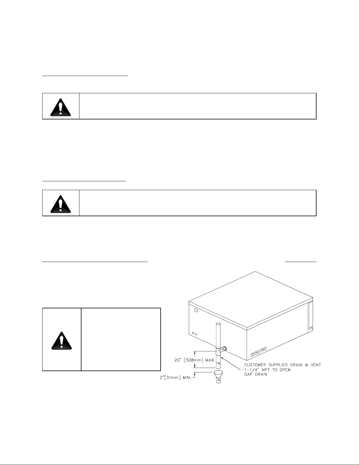
DRAIN CONNECTIONS (FIGURE 2) FIGURE 2
The drain connection must be 1" IPS
vertically down, preferably with one elbow
only, and maximum length of 6 feet, piped
to an open air gap type drain.
CAUTION: In order
to avoid any back
pressure in the
steamer, do not
connect solidly to
any drain connection.

INSTALLATION AND OPERATION MANUAL, GAS FIRED STEAMER,
MODELS RG24-5, SX-34GC, SX-55GC
MANUAL 1195732 REV0 (11/22/2011) 10 HEAVY DUTY STEAM
PLUMBING CONNECTIONS (Continued)
COLD WATER CONDENSER
The steamer is equipped with a cold water condenser in the rear of the cooking chamber which
helps to condense the steam prior to discharge into drain. The steamer freely vents itself by
the negative pressure created by the condensate water drainage. This negative pressure
prevents steam leakage around the door gasket and helps draw the steam through the cooking
compartment. Steam leakage at the door may indicate a plugged or improperly installed drain.
WATER CONDITIONING
It is important that the water supply connected to this steamer be softened to no more than 2.0
grains of hardness and have a pH of 6 to 7.5. This degree of hardness can be easily obtained
with the use of a properly maintained water softener. The use of a water meter will determine
the water consumption and when the water softener needs regeneration or recharging. Failure
to comply with these water condition standards may void the warranty.
Untreated water contains scale producing minerals which can precipitate onto the surfaces in
the boiler. Due to the temperatures in the boiler, the minerals can bake onto the surfaces and
components. This can result in early component failure and reduced product life. Water level
probes become coated with scale. Scale will bridge across the probe insulator from the metal
extension which senses the water level in the boiler shell. Once this scale becomes wet, the
water level control is unable to maintain the proper water level in the boiler.
STRAINERS and FILTERS will NOT remove minerals from the water.
Este manual sirve para los siguientes modelos
2
Tabla de contenidos
Otros manuales de Electrodoméstico de cocina de Southbend

Southbend
Southbend StratoSteam STRE-3EZ Manual de usuario

Southbend
Southbend BECT-24 Manual de usuario

Southbend
Southbend HDO-12 Manual de usuario

Southbend
Southbend GCX-2-6 Manual de usuario

Southbend
Southbend RAPIDSTREAM R2 Manual de usuario

Southbend
Southbend R24-3 Manual de usuario

Southbend
Southbend BELM-30 Manual de usuario

Southbend
Southbend P24-CM Manual de usuario

Southbend
Southbend EZ24-3 Manual de usuario

Southbend
Southbend CM-31 Manual de usuario


