Sound Skulptor CP4500 Manual de usuario
www.soundskulptor.com
Document revision 1.1 – Last modification : 09/12/20
CP 500 Assembly guide
Safety warning
The kits are main powered and use potentially lethal voltages. Under no circumstance should someone undertake the
realisation of a kit unless he has full knowledge about safely handling main powered devices.
Please read the “DIY guide” before beginning.
Print or open the following documents :
• CP 500 Schematics
• CP 500 Components layout
• CP 500 Parts list
• CP 500 Setup guide
Follow this guide from item number 1 till the end, in this order. The assembly order is based on components height, from
low to high profile, in order to ease the soldering process : The component you are soldering is always taller than the
previously assembled ones and it is pressing nicely against the work area foam.
Soldering
All the PCB holes are metallized. It means the connection between the top and bottom pads is already
done. The parts must be soldered only from below (unless differently stated).
Use only small diameter solder, 0.5 or 0.7 mm, 1mm maximum. Use just the minimum necessary amount
of solder. Bad joints are often masked by too much solder.
Cut the component leads and pins totally flush with the PCB after soldering. A too long tail could create
an electric connection with the side plate.
Here are two excellent introduction to soldering videos:
http://www.eevblog.com/2011/06/19/eevblog-180-soldering-tutorial-part-1-tools/
http://www.eevblog.com/2011/07/02/eevblog-183-soldering-tutorial-part-2/
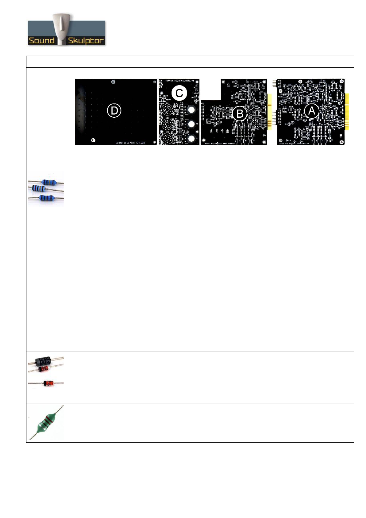
CP 500 Assembly guide – PCB A
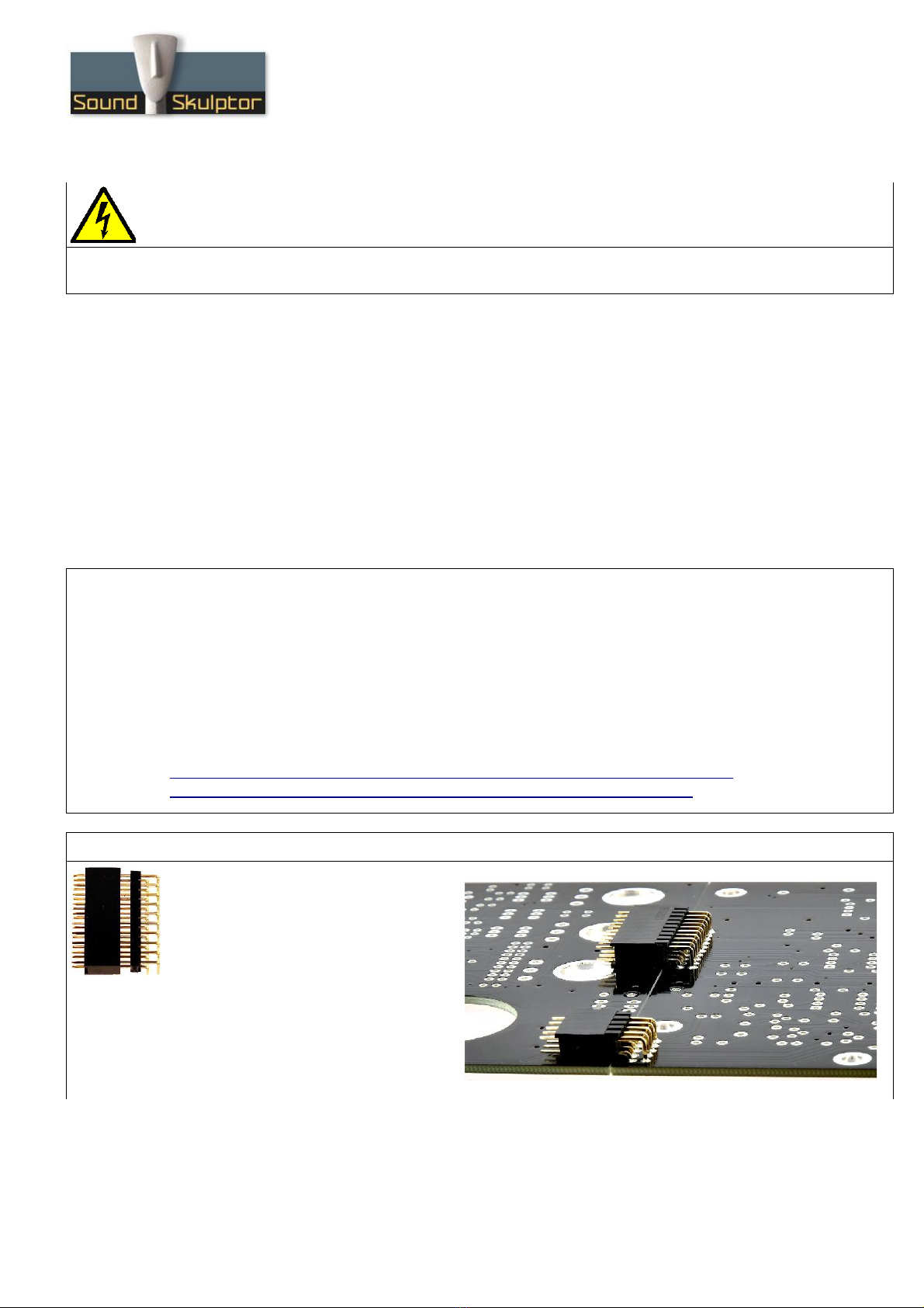
1. PCB to PCB connector CN1A &
CN2A
Insert the female 2x10 connector into
the male part and position the later below
PCB-A on the solder side. The female
connectors must sit flat on its side.
Solder two pins, check position then
solder the other pins.
Do the same for CN2A 2x5 connector.
After soldering remove the female parts.
Copyright ©2019 to Today SoundSkulptor
www.soundskulptor.com
Document revision 1.1 – Last modification : 09/12/20
CP 500 Assembly guide – PCB A
2. PCB split
Split the PCB along the groove. Use extra thin sandpaper to polish all the rough sides.
3. Resistors
Here is a good method for selecting and installing the resistors:
1. pick a row of resistors in the resistors bag,
2. Measure one of the resistors with your DMM,
3. Look up the parts-list PDF for the closest value,
. Check the color code and quantity for confirmation,
5. Use the search function on the Layout PDF page with the resistor value: All the corresponding
resistors are highlighted,
6. Insert and solder.
You can choose to populate the 3 boards one at a time or all together.
In the parts list, the resistor identifiers (Rx) are printed in black for PCB-A, in blue for PCB-B and in
green for PCB-C.
You can use the same method later, for the capacitors.
Add the resistors of board A. Bend the leads at 0. ” with a lead forming tool.
Warning : It is important to check the resistors value with a DMM because the color code can sometimes
be ambiguous. For example 1K (brown-black-black-brown-brown) can be confused with 110R (brown-
brown-black-black-brown).
Warning : When soldering components close to the golden fingers of the edge connector, be very
careful not to touch them with your soldering iron tip. It would cover them with unremovable tin. It is a
good idea to protect them with adhesive tape.
. Diodes
Add D6...D10. Use a lead forming tool to bend the leads at 0. ”.
Add D18.
Add D , D5, D19.
Warning : Make sure to respect the direction of the diodes which is marked by a ring on the component
and a double line on the PCB.
5. Inductor
Add L1.
Copyright ©2019 to Today SoundSkulptor

www.soundskulptor.com
Document revision 1.1 – Last modification : 09/12/20
CP 500 Assembly guide – PCB A
6. IC Socket
Insert and solder the IC sockets: 7 DIL (dual in line) 8 pins, 2 DIL 16 pins and 1 SIL (single in line) 8
pins.
Warning : Make sure to respect the DIL sockets direction, marked by a notch.
7. Relay
Add RLY1.
Warning : Make sure to respect the direction of the relay which is marked by a white line on the
component and on the PCB marking.
8. Ceramic capacitors
Add C13, C , C10, C22, C5, C6.
Add C 8, C 9, C50, C53, C56.
Add C51, C5 , 17 x Cd
9. Test pins
Solder 13 test pins TP1, TP2, TP3, TP , TP5, TP11, TP12, TP13, V+, V-, +12V, -12V and 0V.
The pins are inserted squared shortest end first. They require some pressure to fit. Cut short on the
solder side after soldering.
Copyright ©2019 to Today SoundSkulptor

www.soundskulptor.com
Document revision 1.1 – Last modification : 09/12/20
CP 500 Assembly guide – PCB A
10. Transistor and regulators
Add Q1, U23, U2 .
Warning : Q1 is a device sensitive to static electricity. Make sure your body is grounded before
manipulating simply by removing your shoes.
11. Film capacitors
Add C21, C9, C12, C20, C7, C8.
12. Trimmer potentiometers
Add T1 and T . Solder one pin, check verticality then solder the other pins.
13. Non polarized electrolytic capacitors
Add C11, C1 , C2 , C25, C19, C23.
These caps are not polarized and can be inserted in any direction.
Copyright ©2019 to Today SoundSkulptor

www.soundskulptor.com
Document revision 1.1 – Last modification : 09/12/20
CP 500 Assembly guide – PCB A
1 . Polarized electrolytic capacitors
Add C17, C18, C52, C55, C15, C16
Warning : The +lead must go into the +hole. Do not reverse, it would damage them.
15. 35mm fem/fem Spacer
Insert a M3x6 mm screw from below PCB into the hole
next to Q1. Insert 3 washers on the components side
and attach the M3x35 mm female/female spacer.
16. IC's
Insert the IC's into their respective socket.
On the DIL IC's, the pin 1 is marked by a dot. It must face the white dot on the PCB.
On the SIL IC's, the pin 1 is marked by a notch. It must face the white dot on the
PCB.
Warning : Make sure to insert the IC's in the correct direction.
Copyright ©2019 to Today SoundSkulptor
www.soundskulptor.com
Document revision 1.1 – Last modification : 09/12/20
CP 500 Assembly guide – PCB A
17. Visual check
Brush the solder side with a hard tooth brush to remove any remaining solder bits.
Make a full visual check. When everything looks correct, proceed with PCB B.
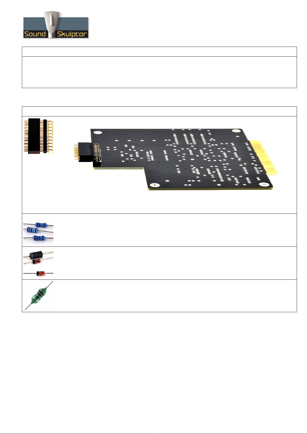
CP 500 Assembly guide – PCB B
18. PCB to PCB connector CN3A
Insert the female 2x10 connector into the male part and position the later below PCB-B on the solder
side. The female connectors must sit flat on its side. Solder two pins, check position then solder the
other pins.
19. Resistors
Add the resistors of board B. Bend the leads at 0. ” with a lead forming tool.
20. Diodes
Add D13 to D17. Bend the leads at 0. ”.
Add D11, D12, D20.
21. Inductor
Add L2.
Copyright ©2019 to Today SoundSkulptor
www.soundskulptor.com
Document revision 1.1 – Last modification : 09/12/20
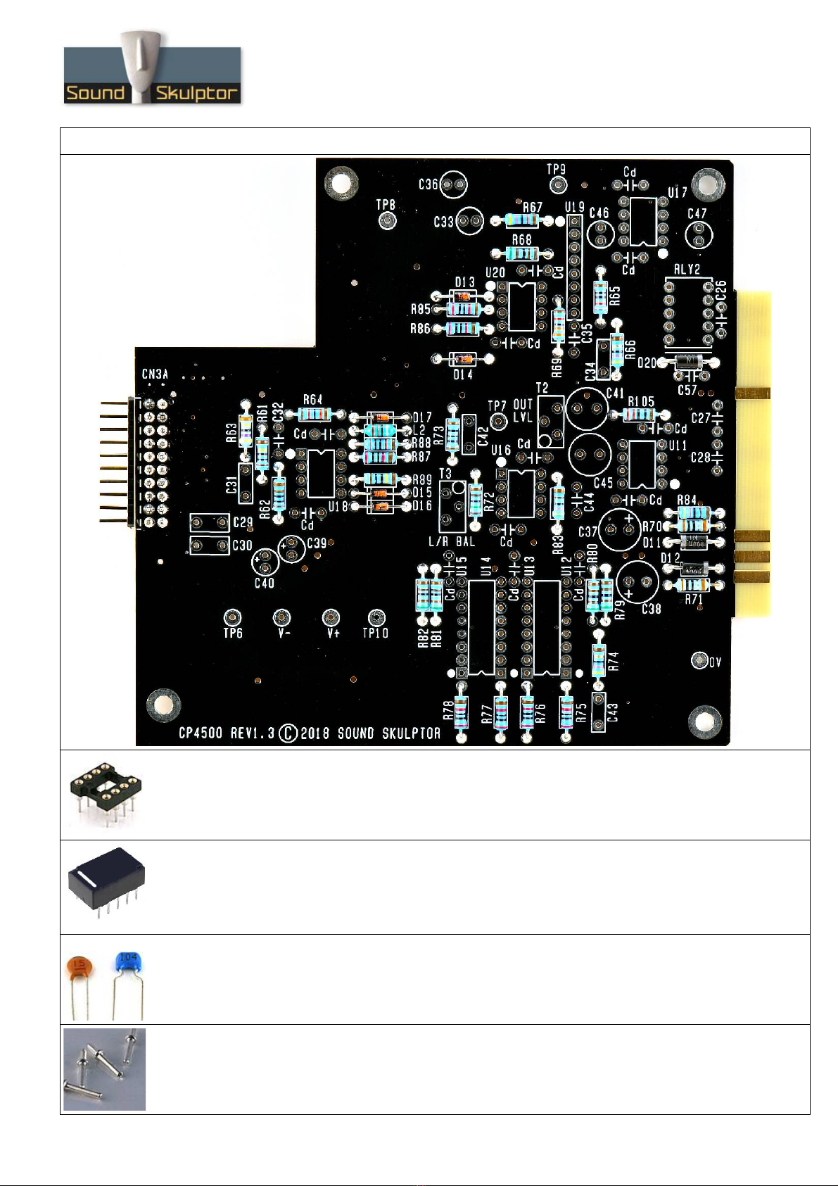
CP 500 Assembly guide – PCB B
22. IC Socket
Insert and solder the IC sockets: 5 DIL (dual in line) 8 pins, 2 DIL 16 pins and 1 SIL (single in line) 8
pins.
Warning : Make sure to respect the DIL sockets direction, marked by a notch.
23. Relay
Add RLY2.
Warning : Make sure to respect the direction of the relays which is marked by a white line on the
component and on the PCB marking.
2 . Ceramic capacitors
Add C35, C26, C32, C , C27, C28.
Add C57.
Add 13 x Cd
25. Test pins
Solder 8 test pins TP6, TP7, TP8, TP9, TP10, V+, V- and 0V.
Copyright ©2019 to Today SoundSkulptor

www.soundskulptor.com
Document revision 1.1 – Last modification : 09/12/20
CP 500 Assembly guide – PCB B
26. Film capacitors
Add C 3, C31, C3 , C 2, C29, C30.
27. Trimmer potentiometers
Add T2 and T3. Solder one pin, check verticality then solder the other pins.
28. Non polarized electrolytic capacitors
Add C33, C36, C 6, C 7, C 1, C 5.
These caps are not polarized and can be inserted in any direction.
29. Polarized electrolytic capacitors
Add C39, C 0, C37, C38.
Warning : The +lead must go into the +hole. Do not reverse.
Copyright ©2019 to Today SoundSkulptor

www.soundskulptor.com
Document revision 1.1 – Last modification : 09/12/20
CP 500 Assembly guide – PCB B
30. IC's
Insert the IC's into their respective socket.
On the DIL IC's, the pin 1 is marked by a dot. It must face the white dot on the PCB.
On the SIL IC's, the pin 1 is marked by a notch. It must face the white dot on the
PCB.
Warning : Make sure to insert the IC's in the correct direction.
31. Visual check
Brush the solder side with a hard tooth brush to remove any remaining solder bits.
Make a full visual check. When everything looks correct, proceed with PCB C.
CP 500 Assembly guide – PCB C
32. Resistors
Add the resistors of board C.
All the resistors on board C are installed vertically.
Copyright ©2019 to Today SoundSkulptor

www.soundskulptor.com
Document revision 1.1 – Last modification : 09/12/20
CP 500 Assembly guide – PCB C
33. Diodes
Add D1, D2. These diodes are installed vertically, cathode (black ring) up.
Warning : Make sure to respect the direction of the diodes which is marked by a ring on the component
and a 'k' on the PCB marking.
3 . Ceramic capacitors
Add C3.
35. Film capacitors
Add C1.
36. Tantalum capacitor
Add C2.
Warning : The +lead must go into the +hole. Do not reverse !
37. Solder side connectors
On the solder side, add CN1B, CN2B, CN3B and
CN .
Copyright ©2019 to Today SoundSkulptor
Otros manuales para CP4500
1
Tabla de contenidos
Otros manuales de Compresor de Sound Skulptor


Manuales populares de Compresor de otras marcas


Emerson
Emerson Copeland Scroll Digital HLR Series Manual de instrucciones

Drawmer
Drawmer 1968 MKII Manual de usuario

Badger Air-Brush
Badger Air-Brush X-Air 80-8 Manual de instrucciones

Omnitronic
Omnitronic CL-166 Manual de usuario

Scheppach
Scheppach HC24V Instrucciones de montaje

Ingersoll-Rand
Ingersoll-Rand centac C950 Manual técnico


