Solwise C1060 Manual de usuario

C
C1
10
06
60
0
I
IP
P
C
Ca
am
me
er
ra
a
O
Op
pe
er
ra
at
ti
in
ng
g
I
In
ns
st
tr
ru
uc
ct
ti
io
on
ns
s
Version V2.0

Trademarks and/or registered trademarks are the property of their respective owners
The information presented in this publication has been carefully
prepared and is believed to be correct at the time of publication.
However, no responsibility will be assumed for any inaccuracies.
Specifications are subject to change without notice.
The information herein is subject to change without notice. This manual
is periodically reviewed and revised.
No responsibility is assumed for any errors or omissions in this
document.

Index
1INTRODUCTION........................................................................................................... - 1 -
1.1 WELCOME TO THE VILAR IP CAMERA .........................................................................- 1-
1.2 PACKAGE CONTENTS ................................................................................................- 1-
1.3 IDENTIFY IP CAMERA ................................................................................................- 1-
2FUNCTIONS AND FEATURES.................................................................................... - 8 -
2.1 BASIC FUNCTIONS ....................................................................................................- 8-
2.2 ADVANCED FEATURES...............................................................................................- 9-
3SYSTEM REQUIREMENT.......................................................................................... - 10 -
4SETUP PROCEDURE.................................................................................................- 11 -
4.1 IP CAMERA POWER &NETWORK CONNECTION ........................................................ - 11 -
4.2 ROUTER/SWITCH/HUB/XDSL MODEM CONNECTION ................................................. - 12 -
4.3 USE IPCAMSEARCH TOOL TO SETUP IP CAMERAS ...................................................- 13 -
4.4 VIEW VIDEO ON WEB BROWSER ..............................................................................- 15 -
4.5 SETUP IP CAMERA ON WEB ....................................................................................- 19 -
4.6 MOUNTING THE IP CAMERA.....................................................................................- 19 -
5SYSTEM CONFIGURATION...................................................................................... - 21 -
5.1 SYSTEM STATUS .....................................................................................................- 21 -
5.2 USER MANAGEMENT ...............................................................................................- 22 -
5.3 NETWORK ..............................................................................................................- 23 -
5.4 DATE AND TIME.......................................................................................................- 24 -
5.5 VIDEO ....................................................................................................................- 24 -
5.6 JPEG ENCRYPTION ................................................................................................- 25 -
5.7 E-MAIL ...................................................................................................................- 26 -
5.8 FTP....................................................................................................................... - 27 -
5.9 SENSORS AND MOTION DETECTION .........................................................................- 28 -
5.10 SCHEDULER TRIGGER .............................................................................................- 29 -
5.11 SYSTEM MAINTENANCE ...........................................................................................- 29 -
5.12 SYSTEM LOG ..........................................................................................................- 30 -
5.13 GUEST VISIT...........................................................................................................- 30 -
6VISIT IP CAMERA OVER INTERNET........................................................................ - 30 -
6.1 WAN IP ADDRESS ..................................................................................................- 31 -
6.2 NETWORK ADDRESS TRANSLATION (NAT)................................................................- 32 -
6.3 PORT FORWARDING ................................................................................................- 33 -
6.4 DEFAULT GATEWAY .................................................................................................- 33 -
6.5 ACCESSING MULTIPLE CAMERAS OVER THE INTERNET ..............................................- 34 -
6.6 DYNAMIC DOMAIN NAME SERVICE (DDNS)..............................................................- 34 -
6.7 CONFIGURATION EXAMPLE ......................................................................................- 35 -
7TECHNICAL PARAMETERS ..................................................................................... - 37 -

Figures and Tables Index
Figure 1 IP Camera 45-angle View................................................................................ - 2 -
Figure 2 IP Camera Front View ..................................................................................... - 2 -
Figure 3 IP Camera Back View...................................................................................... - 3 -
Figure 4 Front View Indication and Operation ............................................................... - 3 -
Figure 5 LCD Indications ............................................................................................... - 4 -
Figure 6 IP Address/Network Mask/Gateway loop show ............................................... - 4 -
Figure 7 Back View Indication........................................................................................ - 6 -
Figure 8 Input & Output defines ..................................................................................... - 6 -
Figure 9 Input & Output Pins Connection ...................................................................... - 7 -
Figure 10 Insert a CF Card ............................................................................................ - 8 -
Figure 11 Connecting the Ethernet wire....................................................................... - 11 -
Figure 12 connecting the power supply ....................................................................... - 11 -
Figure 13 LAN connection ........................................................................................... - 12 -
Figure 14 IP Camera Search Tool................................................................................ - 13 -
Figure 15 Modify IP Camera’s IP Address ................................................................... - 14 -
Figure 16 Input Administrator’s Username and Password .......................................... - 14 -
Figure 17 IP Camera Home Page................................................................................ - 15 -
Figure 18 Login Message box...................................................................................... - 16 -
Figure 19 IE Security Warning ..................................................................................... - 16 -
Figure 20 Security setting for ActiveX Controls ........................................................... - 17 -
Figure 21 Set IP Camera as a trusted site................................................................... - 18 -
Figure 22 Video webpage ............................................................................................ - 18 -
Figure 23 History Images View .................................................................................... - 19 -
Figure 24 System Status View ..................................................................................... - 21 -
Figure 25 User Management View .............................................................................. - 22 -
Figure 26 Network Setup View .................................................................................... - 23 -
Figure 27 Date and Time Setup View .......................................................................... - 24 -
Figure 28 Video Setup View......................................................................................... - 24 -
Figure 29 JPEG Encryption Setup View ...................................................................... - 25 -
Figure 30 Require Password Input in Client Web Browser.......................................... - 25 -
Figure 31 Input Password in Web Browser (ActiveX).................................................. - 26 -
Figure 32 Input Password in Web Browser (Java).................................................... - 26 -
Figure 33 E-mail Setup View ....................................................................................... - 26 -
Figure 34 FTP Setup View ........................................................................................... - 27 -
Figure 35 Sensors and Motion Detection Setup View ................................................. - 28 -
Figure 36 Scheduler Trigger Setup View ..................................................................... - 29 -
Figure 37 System Maintenance View .......................................................................... - 29 -
Figure 38 System Log View ......................................................................................... - 30 -
Figure 39 “Guest Zone” View....................................................................................... - 30 -
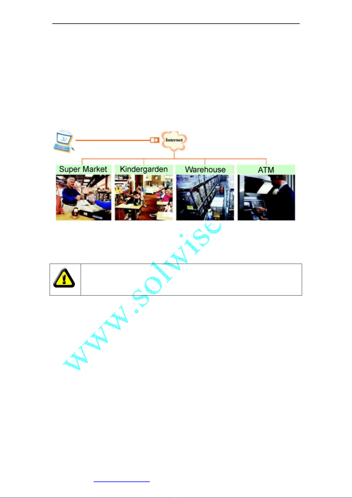
Figure 40 IP Camera’s Application Environment ......................................................... - 31 -
Figure 41 Typical Network Environment ...................................................................... - 35 -

1 Introduction
1.1 Welcome to the Vilar IP Camera
The Vilar IP Camera combines a high quality digital video camera with network
connectivity and a powerful web server to bring clear video to your desktop from
anywhere on your local network or over the Internet.
1.2 Package Contents
Your IP Camera package should contain the following items, If any of the
listed items are missing, please contact your reseller from where you
purchased the camera for assistance.
The package includes.
1. IP Camera *1
2. IP Camera Utility CD *1
3. 5V Power Adapter *1
4. Dynamic DNS Registration Card *1
5. Ceiling Mounting bracket *1
1.3 Identify IP Camera
1.3.1 IP Camera Views

Figure 1 IP Camera 45-angle View
Figure 2 IP Camera Front View
Working Status LED
User Visiting LED
Privacy Indicate LED
Privacy Status Button
IP Show LCD
Lens
Night Vision LEDs
Tilt
Pan

Figure 3 IP Camera Back View
1.3.2 Indication and Operation
Figure 4 Front View Indication and Operation
The privacy button toggles Privacy mode and Normal mode, In Privacy mode, all the
remote users will not be allowed to see the video.
LED: Privacy
Button: Privacy
LED: User Visiting
LED: Working
LCD
CF Card Socket
RESET Button
Input&Output Pins
RJ45 Ethernet Socket
DC 5V Input Socket

Figure 5 LCD Indications
LCD will loop show IP Address/Network Mask/Gateway, as shown in the Figure 6.
Figure 6 IP Address/Network Mask/Gateway loop show
Status icon indications list:
Icon Meaning
IPAddress=192.168.0.24 Subnet mask=255.255.255.0 Gateway IP=192.168.0.1

DDNS Server Registered. Connected to the INTERNET
successfully.
Vilar Backbone server connected successfully.
There is/are user(s) visiting IP Camera video.
Sensor triggered. (Digit input or Motion detection)
CF card detected.
System in configuration status. E.g. Upgrading firmware.
Network mode indications:
Icon Meaning
Static IP Use static (manually fixed) IP mode.
DHCP IP Address is dynamically assigned by DHCP
Server.
PPPoE IP Camera’s internal PPPoE dial function
enabled.(Used for xDSL)
Working status LED meaning:
LED Status Meaning
Normal Flashing:
Turns on for 1/2 second every 3 seconds
Normal running
Always on or always off System error
Fast Flashing:
Turns on for 1/2 second every 1 second
System is starting, Please wait.
Slow Flashing:
Turns on for 1/2 second every 6 second
Upgrading firmware, Please wait.

Figure 7 Back View Indication
Figure 8 Input & Output defines
Input Pins: The input pins can be used for 2-way external sensor input. For example,
you may connect a Person Infrared Sensor (PIR) to it for motion detection. When
CF Card Socket
Reset button
Input & Output Pins
RJ45 Ethernet Socket
DC 5V Input Socket
Output Pins
Relay: Normally Open
Digit Input Pins
Output
A B
Input Common Input
1 2
1 2 3 4 5
Tabla de contenidos
Otros manuales de Cámara IP de Solwise


