SolutionAir elicent REC-Duo 100 Manual de usuario

Page 1 / 17
Heat recovery unit
Instruction Manual
ENGLISH v1.4
WARNING: The equipment must only be installed by a specialised technician!
Read and apply the manual before carrying out the installation.
Keep this manual in a safe place.

Page 2 / 17
Dear Customer,
The product you purchased is a heat recovery extractor fan without ducting, suitable for wall mounting. To
ensure optimum operation and a long life, read this manual carefully in order to correctly install, use and
maintain the product. Following all the instructions ensures reliability and long life, both mechanically and
electrically.
The manufacturer declines any responsibility for damages, caused to persons or things, caused by failure to
observe the following instructions.
The product is constructed using state of the art technology and respects the standards in force regarding
electrical equipment. It conforms with the EMC European Directive in force regarding radio interference
suppression and electro- magnetic compatibility.
Contents
WARNING ADVICE ........................................................................................................................................................ 3
TROUBLESHOOTING ....................................................................................................................................................... 4
DISMANTLING AND RECYCLING ................................................................................................................................. 4
PRODUCT DESCRIPTION................................................................................................................................................ 4
OPERATING PRINCIPLE.................................................................................................................................................. 5
DIMENSIONS.................................................................................................................................................................... 5
BOX CONTENTS .............................................................................................................................................................. 6
INSTALLATION DIAGRAM.............................................................................................................................................. 7
INSTALLATION LOCATION............................................................................................................................................. 8
INSTALLATION ADVICES ................................................................................................................................................ 8
WIRING DIAGRAM ....................................................................................................................................................... 10
TIMER AND HUMIDISTAT .............................................................................................................................................. 11
SPEED SELECTION......................................................................................................................................................... 12
FIRST START-UP - PAIRING ............................................................................................................................................ 12
REMOTE CONTROL ...................................................................................................................................................... 13
SPECIFIC FUNCTIONS OF THE REMOTE-CONTROL REC DUO 100 PLUS RC ........................................................ 14
MODESL & OPERATION............................................................................................................................................... 15
LEGEND OF THE VENTILATION UNIT STATUS ............................................................................................................. 16
CLEANING AND MAINTENANCE............................................................................................................................... 17
RESETTING THE REPLACE/CLEAN FILTERS NOTICE (RED FLASHING LED)............................................................. 17
CUSTOMER SERVICE .................................................................................................................................................... 17

Page 3 / 17
WARNING ADVICE
WARNING: Serious injury or death can be caused if these instructions are not applied!
Do not use this product for uses that are different from those for which it has been designed.
After removing the product from its packaging ensure that it is complete and undamaged; if in doubt,
immediately contact a qualified electrician.
Do not leave parts of the packaging within reach of children or incompetent persons. To dispose of the
packaging and the appliance at the end of its useful life refer to the recycling norms in force in your country.
Immediately contact a qualified person (authorised dealer or the manufacturer) if the product is dropped or
knocked to check its correct functioning.
Do not touch the appliance with wet or humid parts of the body (e.g., hands or feet).
This appliance can be used by children aged from 8 years and above and persons with reduced physical, sensory
or mental capabilities or lack of experience and knowledge if they have been given supervision or instruction
concerning use of the appliance in a safe way and understand the hazards involved. Children shall not play with
the appliance. Cleaning and user maintenance shall not be made by children without supervision.
The means of disconnection from the supply mains must have a contact separation in all poles and must provide
full disconnection under overvoltage category III conditions.
If there is a combustible-fed device (water heater, gas boiler, etc. of the sealed chamber type) in the room
where the product is to be installed check that the re-circulation of air is sufficient to ensure a good combustion
for the correct functioning of these devices, precautions must be taken to avoid the back-flow of gases into the
room from the open flue of gas or other fuel-burning appliances.
To avoid the risk of fire do not using the product in the presence of inflammable
substances and vapours, such as alcohol, insecticides, petrol, etc.
The product can be connected to the supply mains only if the voltage and the frequency of the supply mains
correspond to those written in the rating label.
In the case of malfunction, anomaly or any type of fault disconnect the appliance from the electrical main
supply and contact a qualified person. Use only original spare parts for repairs.
The electrical system to which the appliance is connected must conform with the local norms in force regarding
electrical systems.
The appliance must not be used to activate water heaters, room heaters, etc.
DO NOT INSTALL ON THE CEILLING.
WARNING: Damage can be caused to the device if the following instructions are not applied!
Do not use the product at environmental temperatures more than 40°C.
Do not leave the appliance exposed to atmospheric agents (rain, sun, snow, etc.). The possible applications of
this product are illustrated in this manual.
Do not submerge the equipment or any of its parts in water or other fluids, unless specifically required by
maintenance operations.
When cleaning or carrying out ordinary maintenance, check the integrity of the appliance.
The flow of air or fumes that is conveyed by the appliance must be clean and free of greasy elements, soot,
chemical/corrosive agents and inflammable or explosive mixtures.
Do not obstruct the air inlet and outlet of the appliance in any way whatsoever.
When using air ducting make sure that the ducting is not blocked.
For an optimum functioning of the appliance, it isnecessary to ensure an adequate re-circulation of air in the
room. Consult the local norms with regards to this.

Page 4 / 17
TROUBLESHOOTING
PROBLEM
CAUSE AND REMEDY
The appliance does not switch on
There is no voltage.
Check the main switch and/or the electrical connections.
The impeller does not turn
Check that its movement is not obstructed.
This device is equipped with a manual reset protection system
that in the event of a mechanical obstruction in the rotation will
switch off the engine.
To restore normal operation, proceed as follows:
disconnect the device from the power mains upstream;
remove the cause of the mechanical obstruction (only
qualified
personnel);
reconnect the device to the power mains.
The device will only resume normal operation if the protection
system does not detect any additional faults. If the fault persists,
contact the client support service.
The devices on the PLUS RC version
do not synchronise
Disconnect and reconnect power supply.
The remote control does not work
(only in the Plus RC version)
Check the status of the battery.
DISMANTLING AND RECYCLING
If a crossed-out wheeled bin is illustrated on a product, this means that the product satisfies the
requirements of the 2012/19/UE European Directive.
Conform to the local norms regarding the disposal of waste materials and do not dispose of old
products in normal domestic waste material.
PRODUCT DESCRIPTION
The product is a single hole, heat recovery unit without ducting, suitable for single rooms.
The heat is recovered by means of a ceramic exchange that acts as a heat accumulator. In the normal
operating cycle, the device expels stale air from the inside outwards (extraction); in this first phase the air passes
through the recuperator transferring heat to the ceramic core. In the second phase of the cycle the air flow is
reversed (intake): the external air passes through the heat exchanger capturing the previously accumulated
heat before being transferred inside. This operation alternates the flow every 60 seconds (Push-Pull).

Page 5 / 17
OPERATING PRINCIPLE
Extraction Cycle (Push) Intake Cycle (Pull)
60 seconds 60 seconds
DIMENSIONS
Main Unit –REC-Duo 100
EXTERNAL VENT EXTERNAL COWLING (PLENUM)

Page 6 / 17
BOX CONTENTS
5
6
2x
7
2
3
4
1
17
11
12
13
8
9
10
15
14
1. Ventilation Unit
2. Power supply plate cover
3. Power supply plate
4. External vent (2 parts)
5. Telescopic tube
6. Ceramic heat exchanger
7. Filters (already assembled on the heat exchanger)
8. Screws for fixing the wall power supply plate cover
9. Wall plugs
10. Screws for fixing power supply plate
11. Awl key for "RESET” button
12. Remote Control (1pc, RC version only)
13. Mounting Kit for Remote Control (RC version only)
14. Trade Seal
15. External cowling (plenum)
16. Wall mounting bracket
17. Documentation (Manual, Technical Product Page,
International Warranty, ErP Label)
16

Page 7 / 17
INSTALLATION DIAGRAM
Notes
−If total wall thickness is greater than 22cm, it can be considered to install the duct without
cowling.
−For retrofit projects we recommend to use always the cowling to allow a correct installation
of the trade seal.
−The ‘Wall Mounting Bracket’ and the REC-Duo ‘Power Supply Plate’ should be at least fixed
with 2 screws to the timber/ steel frame.

Page 8 / 17
INSTALLATION LOCATION
The location of the installation should preferably meet following requirements:
−High position in the room on the wall (above 2m height)
−Next to a timber/steel wall frame (to fix the wall mounting bracket)
−Reasonable sheltered place from outside (from wind, rain, sun)
−Away from bedhead to reduce noise disturbance during the night
−Suitable for wiring from and to wall switch
INSTALLATION ADVICES
Wall Mounting Bracket Hole Diameter 110 mm
External Waterproof Membrane & Tube External Cowling (Plenum)
Drill or cut a 110mm hole through wall with a
2° slope towards outside.
(If required, remove temporary the wall
mounting bracket)
Choose location and install wall mounting
bracket from inside before installing the gib
board.
Install duct and trade seal from outside
with a 2° slope for weathertight connection.
Install external cowling from outside with the
bigger hole against the trade seal and the
slope on the top. Consider to drill a small
drain hole if cowling is exposed to rain.
Page 9 / 17
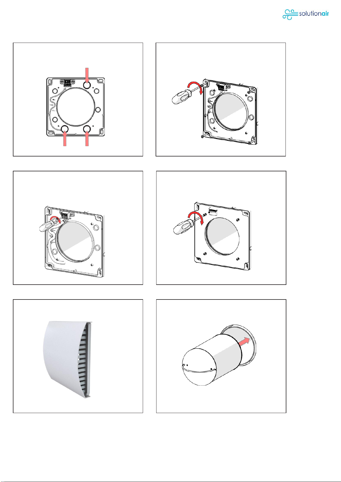
Wiring to and from switch Power Supply Plate
Electrical Connection Power Supply Plate Cover
External Vent Ceramic Core
Plan wiring from and to wall switch:
3 options to go through power supply plate.
(Switch is not included)
After installing the gib board over the
mounting wall bracket, cut out the whole
and line up the power supply plate on top.
Connect power supply plate in
accordance with wiring diagram.
(Only certified electricians)
Install power supply plate cover.
Install external vent on the cowling. Insert ceramic core into duct from inside.

Page 10 / 17
REC-Duo Unit External Cladding
WIRING DIAGRAM
Wiring diagram for 24h/7d operation
It is recommended to include a main switch to power off the whole unit for e.g. maintenance.
Insert the REC-Duo unit into the duct. The
power connectors need to line up and the
plate snaps into a magnetic mount.
Complete external cladding around the
cowling in accordance with NZ building
standards.
REC-Duo 100
REC-Duo 100 MHY
REC-Duo 100 RC PLUS
Este manual sirve para los siguientes modelos
2
Tabla de contenidos


