Sol TP Series Instrucciones de instalación

TP Series
Top of Pole Mount Solar LED Lighting System
Triple and Quad PV Mounting
Installation and
Owner’s Manual
rev.1011 MKTG-IM-TP-34-002

2 rev.1011 MKTG-IM-TP-34-002
Installation and Owner’s Manual | TP Series Solar LED Lighting System
Contents
Important Notes and Warnings
This installation and instruction manual provides installation, operation, and maintenance
instructions for the Sol TP Series solar LED lighting system. The entire contents of this
manual should be thoroughly reviewed and understood prior to installing this equipment.
Do not discard this manual, as it contains complete maintenance instructions, a
troubleshooting chart, and a spare parts list. To insure proper operation of this equipment,
it is important that the equipment be utilized for its intended use. Any use of this
equipment for purposes other than those intended will void all warranties.
Installation and/or troubleshooting should be performed only by qualified
personnel. Follow local codes at all times during installation of the TP system.
Be very careful when working with batteries.
Do not allow bare ends of the wires to touch each other or grounded metal
parts while connected to the controller. This will damage the controller.
This manual contains important instructions for the Sol TP Series that shall be
followed during installation and maintenance of the charge
controller.
1.0 Introduction .................................................. 3
1.1 Operational Principles ............................ 3
1.2 System Overview ................................... 3
2.0 Installation .................................................... 4
2.1 Site Selection and Preparation ............... 4
2.2 Unpacking and Inspection ...................... 5
2.3 PV Assembly & Adaptor Mounting ......... 5
2.4 Mounting TP Assembly to Pole .............. 6
2.5 Drilling Mounting & Access Holes ........... 7
2.6 Mounting Battery Enclosure & Channel .. 8
2.7 Routing PV & Luminaire Cables .............. 9
2.7 Attaching Controller to Battery Box ........ 9
2.8 Attaching the LED Fixture to the Arm ... 10
Attaching the Cobrahead Fixture ......... 10
Attaching the Shoebox Fixture ............. 10
LED Fixture Precautions ....................... 11
2.9 Installing the NRGLife™ Battery ........... 11
2.10 Connect Components to Controller .... 12
Connecting Components (cont) ......... 13
Connecting Components (cont) ......... 14
2.11 Testing the System ............................. 15
3.0 Operation and Maintenance ........................ 16
3.1 Break-in Period .................................... 16
3.2 Expected Performance ......................... 16
3.3 Preventive Maintenance and Service .... 17
Tree Branch Clearing ........................... 17
Fuse Replacement ............................... 17
LED Fixture Replacement .................... 17
Battery Replacement ........................... 18
3.4 Troubleshooting Chart .......................... 18
Frequently-Asked Questions ................ 19
In-Warranty Service Instructions ........... 19

3 rev.1011 MKTG-IM-TP-34-002
Installation and Owner’s Manual | TP Series Solar LED Lighting System
LED Luminaire
FIGURE 1 SYSTEM OVERVIEW
PV Module(s) -
Panel Pans are
optional
Pole (Provided by Customer)
Battery Enclosure**
(B.E.) May be
located near top
or Bottom of pole.
Houses intelligent
Controller and one
or more NRGLife™
Batteries
PV Mounting TP Assembly
Tenon Adaptor
Arm (Universal shown)
Battery Enclosure Channel
(B.E. Channel)
1.0 Introduction
This manual contains important instructions for the TP Series - 3 or 4 panel systems that
shall be followed during installation and maintenance of the charge controller.
The TP Series is a patented, off-grid, standalone, solar-powered lighting system. Years
of engineering, development, and testing ensure that this system meets or exceeds all
performance and reliability specifications. Every system that leaves our factory has been
quality control tested and inspected to assure you of an easy installation and highly
dependable performance. All mechanical fittings and electrical connections are designed
for simple and reliable installation. The system is ready for use immediately after the
components are mounted and the plug and play connectors are joined.
1.1 Operational Principles
The Sol TP Series solar LED lighting system is designed to provide reliable operation and
illumination all year. The solar array (the photovoltaic panel, or PV panels) re-charges the
battery each day, replacing energy that was used during the previous evening so that
illumination can again be provided during the following evening. The system is designed
with a reserve, so that regular illumination will continue to be provided during periods
of rainy or cloudy weather. The controller monitors battery condition and will shut off
illumination if the battery charge drops below a specified level. This may occur if there is
a prolonged rainy or cloudy weather or if the solar array is shaded during part of the day.
The controller automatically restarts the system when the condition is corrected and the
battery charge returns to the specified level, protecting the batteries.
** Battery Enclosure may be
provided with hinged cover
and optional locking device.
1.2 System Overview
Hardware components of the
Sol TP Series lighting systems
are shown in Figure 1.
There are several models
of the Sol TP Series lighting
system.
The models are identical
except for the size of the solar
panel, which is specified for
your location and the fixture
choice.
4 rev.1011 MKTG-IM-TP-34-002
Installation and Owner’s Manual | TP Series Solar LED Lighting System
2.0 Installation
Install the Sol TP Series lighting system in accordance with all applicable building codes.
Though designed for ease of installation, it is recommended that the Sol TP Series lighting
system be installed by a licensed electrician.
The Sol TP Series lighting system is manufactured to comply with Article 690
of the National Electric Code. Please consult with your local building authority
for requirements that are specific to your area.
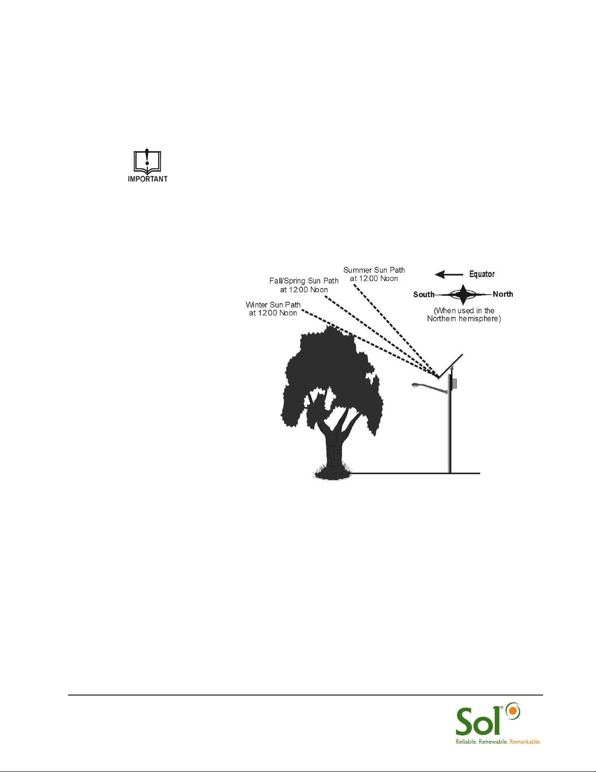
2.1 Site Selection and Preparation
Locate and
install the PV
panels in an area where
they can face the
equator (due south
in the Northern
hemisphere) and will
not be shaded by trees,
poles, buildings, or
other objects during the
day (Figure 2).
Installing in a location
where the solar
panels are shaded
during part of the
day will prevent the
solar panel from fully
charging the battery, reducing the hours of nighttime illumination and possibly damaging
the battery.
Before installing near a tree, 1) verify that the municipality allows tree trimming and,
2) understand that the tree branches will likely need to be trimmed on a regular basis.
Do not locate in an area where there is excessive ambient or reflected light at night which
may simulate daylight and cause the system controller to turn off the system.
FIGURE 2 LOCATING & POSITIONING PV PANELS

5 rev.1011 MKTG-IM-TP-34-002
Installation and Owner’s Manual | TP Series Solar LED Lighting System
TABLE 1 LIST OF FASTENERS
2.2 Unpacking and Inspection
The Sol TP Series lighting system is shipped as a complete kit. Prior to assembly,
remove the entire contents of the kit from the packaging and check the contents of the kit
against the Packing list you received in the ”OPEN FIRST” envelope.
The fasteners that are provided with the parts and components and the torque to which
each type of fastener should be tightened is shown Table 1.
Refer to packing list for complete parts and call Sol Customer Service at
+1.772.286.9461 if any components or hardware are missing,
* Recommended Torque
2.3 PV Panel Assembly and Adaptor Mounting
1. Lay PV panels side by side on cardboard packaging to protect surface of PV
panels.
2. Place TP assembly in center of panels. Place top and bottom “Z” struts lining
up screw holes with TP assembly. Secure TP assembly with 4x 5/16-11 x 3”
screws.
3. Align slots in Z-strut with pre-drilled PV module holes and secure “Z” struts to PV
panels using 16x 5/16-11 x 3/4” security screws. (Figure 3).
Fastener Qty. Torque* Qty. Torque*
5/16-18 x 3” screw (2 washers/lock washer/nut) 7 ‘A’ 11 ft. lbs 5/8-11 x 10” bolt (2 washers/lock
washer/ nut)
2 ‘L’ 93 ft. lbs
5/16-11 x 1” screw (2 washers/lock washer/nut) 18 ‘A’ 11 ft. lbs
5/8-11 x 6” bolts (2 washers/lock washer/ nut) 3 ‘A’ 93 ft. lbs 3/4-10 x 12” bolt (2 washers/lock
washer/ nut)
2 ‘B’ 93 ft. lbs
3/8-16 x 1/2” cup point screw 3 ‘A’ 20 ft. lbs 1/4–20 x 1/2” hex head bolt 4 ‘B’ 6.3 ft. lbs
A - Part of TP fastener kit B- Part of Battery fastener kit
L - Loose part Extra 5/16 fasteners included
Orientation of PV J-boxes should be
at top end of tilted panel
FIGURE 3 MOUNTING PV PANELS TO TP ASSEMBLY
16x
4x

6 rev.1011 MKTG-IM-TP-34-002
Installation and Owner’s Manual | TP Series Solar LED Lighting System
4. Place TP assembly over tenon adaptor and ensure PV module is angled at 45°
or designated angle for your location. Top bolt determines angle.
5. Secure tenon adaptor to TP mount with 2 x 5/8-11 x 6” screws (Figure 4).
6. Connect MC connectors to PV Arrays and route PV harness through tenon
adaptor.
2.4 Mounting TP Assembly to Your Pole
1. Place TP Assembly with tenon adaptor into pole (facing Equator) and match drill
hole in tenon with tenon adaptor.
2. Secure with a 5/8-11 x 6” bolt and 3x 3/8-16 x 1/2” cup point set screws
(Figure 5).
FIGURE 4 SECURING TP TENON ADAPTOR
FIGURE 5 MOUNTING TP ASSEMBLY TO POLE
PV Modules- Always facing
EQUATOR (South in Northern Hemisphere)
NS
x 3
45°
30°
60°
15°
MC Connectors PV Harness can be routed outside
or through tenon adaptor and pole.

7 rev.1011 MKTG-IM-TP-34-002
Installation and Owner’s Manual | TP Series Solar LED Lighting System
2.5 Drilling Mounting and Access Holes in Pole
1. Drill thru .87” diameter holes for B.E. mounting in desired location using B.E.
Channel as guide.
2. Drill thru one side a 1.25” access hole for PV and Luminaire connectors 4.25”
below top B.E. Channel hole (Figure 6).
3. Determine desired location of fixture arm and drill mounting holes for fixture arm
by using arm bracket as template (Figure 7).
4. Drill access hole to route Luminaire wiring to B.E. Enclosure (Figure 7a). Sol will
provide template for concrete pole manufacturing.
5. Secure arm with 2x 5/8-11 x 10” bolts.
For Wood or Concrete Poles A separate addendum will be provided
for each. Contact Sol if you are installing a wood or concrete pole.
FIGURE 7a DRILL TEMPLATE - ARM
FIGURE 6 DRILLING B.E. MOUNT & ACCESS HOLES
FIGURE 7 DRILLING FIXTURE ARM
MOUNTING & ACCESS HOLES
Helpful Hint#1: If mounting two
arm mounts, connect both using
the same bolts.
Battery Enclosure
Channel holes: Drill
thru @.87 Dia.
Access hole for PV &
Luminaire harness to B.E:
Drill thru one side @ 1.25”
Dia. Approx. 4.25” below
top B.E. Channel hole.
28”
6” Min. from top of pole
Arm Mounting Hole
Drill thru 2x @.75”Dia.
Access hole for
Luminaire harness
Drill thru one side
@ 1.25” Dia.

8 rev.1011 MKTG-IM-TP-34-002
Installation and Owner’s Manual | TP Series Solar LED Lighting System
2.6 Mounting Battery Enclosure (B.E.) and B.E. Channel
1. Secure B.E. channel using 2x 3/4-10 x 12” bolts.
2. Loosely fasten 4x 1/4”–20 x 1/2” hex head bolts to the B.E. Channel.
3. Route PV and LED cables through B.E. into the access holes on the battery box
(see next step).
4. Mount B.E. on bolts and securely tighten each bolt. (Figure 8).
Helpful Hint #2: Wrap harness
plugs together with tape to
easily pull them through the
drilled hole.
Helpful Hint #3: If mounting
Battery Enclosure near base of
pole, extension harnesses will be
supplied
FIGURE 8 MOUNTING B.E. & ROUTING CABLES
2x
4x
Wiring hole for PV &
LED harness
PV Harness to/from B.E.
Luminaire Harness to/from B.E.
Battery Enclosure
(B.E.)
B.E. Channel

9 rev.1011 MKTG-IM-TP-34-002
Installation and Owner’s Manual | TP Series Solar LED Lighting System
2.7 Routing PV & Luminaire Cables
1. Open Battery Enclosure.
2. Insert the PV cable and Luminaire cables into access hole on the battery
enclosure, as shown in Figure 9.
3. Position the cables so they extend inside the battery box at least 12 inches (30.5
cm).
Your battery enclosure may include a hinged cover and an
optional locking key device.
FIGURE 9 MOUNTING B.E. & ROUTING CABLES
Cables from LED
Luminaire & PV
Module
FIGURE 10 MOUNTING CONTROLLER
Flush studs for hardware
Controller
2.7 Attaching Controller to Battery Enclosure
1. The controller needs to be installed on the inside of the battery box cover.
2. Remove controller from packaging and remove hardware on controller.
3. Place controller on battery box cover over flush studs and secure with supplied
hardware (Figure 10).

10 rev.1011 MKTG-IM-TP-34-002
Installation and Owner’s Manual | TP Series Solar LED Lighting System
2.8 Attaching the LED Fixture to the Arm
Two types of LED fixtures are provided with the SH Series lighting system:
Attaching the Ascot Fixture to the Arm
1. Loosen fastener that secures hinged cover to fixture; lift cover and loosen
mounting clamp bolts. Route the connector wire from the mounting arm through
the fixture mounting clamp, and plug luminaire connectors together (11a).
2. Slide the fixture mounting clamp over the mounting arm (11b) and adjust the
angle by positioning the fixture so the appropriate tilt step rests on the end of the
mounting arm (11c).
3. Tighten the mounting clamp bolts (do not over tighten) to secure the fixture to
the mounting arm then close the hinged cover and secure it to the fixture).
Attaching the Shoebox Fixture to the Arm
1. Loosen the two set screws on the Shoebox fixture (Figure 12a).
2. Plug the Shoebox fixture connector into the load cable connector.
3. Slide the Shoebox fixture over the arm. Feed any excess load cable back into
the arm while sliding the fixture over the arm.
4. Remove the circular cover (using a Phillips screwdriver) and loosen the bolt
(using a socket wrench) to change the angle of the fixture (Figure 12b). Tighten
the bolt and replace the cover when completed.
FIGURE 12 ATTACHING THE SHOEBOX FIXTURE TO THE ARM
(a) (b)
Set Screws
FIGURE 11 ATTACHING THE COBRAHEAD
FIXTURE TO THE ARM
(a) (b)
(c)
Cobrahead
Fixture
Shoebox
Fixture
Tabla de contenidos


