SnapAV Dragonfly Manual de usuario
INSTALLATION MANUAL
Motorized Tab Tension Projection Screen
Pg. 2
© 2013 Dragony
DFM-TAB Installation Manual
1. Important Safety Precautions and Warnings
To reduce the risk of re or electric shock, do not expose this apparatus to rain or moisture.
The lightning ash with arrowhead symbol, within an equilateral
triangle, is intended to alert the user to the presence of un-
insulated dangerous voltage within the product’s enclosure that
may be of sufcient magnitude to constitute a risk of electric
shock to persons.
The exclamation point within an equilateral triangle is intended
to alert the user to the presence of important operating
and maintenance (servicing) instructions in the literature
accompanying the appliance.
1. Read and follow all instructions and warnings in this manual. Keep for future reference.
2. Do not use this apparatus near water.
3. Clean the screen housing only with a dry cloth.
4. Do not block any ventilation openings. Install according to manufacturer’s instructions.
5. Do not install near any heat sources such as radiators, heat registers, stoves or other apparatus (including
ampliers) that produce heat.
6. Do not override the safety purpose of the polarized or grounding-type plug. A polarized plug has two blades - one
wider than the other. A grounding type plug has two blades and a third grounding prong. The wide blade or the
third prong is provided for your safety. If the provided plug does not t into your outlet, consult an electrician for
replacement of the obsolete outlet.
7. Protect the power cord from being walked on or pinched particularly at plug, convenience receptacles, and the
point where it exits from the apparatus.
8. Only use attachments/accessories specied by the manufacturer.
9. Use only with a cart, stand, tripod, bracket or table specied by the manufacturer, or sold with the apparatus.
When a cart is used, use caution when moving the cart/apparatus combination to avoid injury from tip-over.
10. Unplug this apparatus during lightning storms or when unused for long periods of time.
11. Refer all servicing to qualied service personnel. Servicing is required when the apparatus has been damaged in
any way, such as when the power-supply cord or plug is damaged, liquid has been spilled or objects have fallen
into the apparatus, the apparatus has been exposed to rain or moisture, does not operate normally, or has been
dropped.
12. Do not expose this equipment to dripping or splashing; ensure that no objects lled with liquids, such as vases,
are placed on the equipment.
13. To completely disconnect this equipment from the AC mains, disconnect the power supply cord plug from the AC
receptacle.
Warning:
CAUTION
CAUTION: TOREDUCE THE RIS K OF
ELECTRICAL SHOCK.
DONOT REMOVE COVER. NOUSER
SERVICEABLE PARTS INSIDE.
REFER S ERVICING TOQUALIFIED
SERVICE PERSONNEL.
Before you unpack the projection screen, read the entire manual to become familiar with the steps
involved for installation and operation. If you feel uncomfortable performing any of the steps
required, stop and consult a qualied installation professional. Dragony is not responsible for
any damage or injury that occurs from incorrect installation or operation.

DFM-TAB Installation Manual
Pg. 3
www.snapav.com Support: 866.838.5052
1. Important Safety Precautions and Warnings
Table of Contents
2. Overview
3. Package Contents
4. Pre-Installation
4.1. Required for Installation
4.2. Unpacking the Projection Screen
4.3. Powering the Screen
4.4. Mounting Considerations
4.5. Control Method
5. Installation
5.1. Installing the Brackets
5.1.1. Mounting Brackets
5.1.2. Hanging Mount
5.2. Installing the Screen on the Brackets
5.3. Test the Screen
6. Control Setup
6.1. Control Wiring Diagram
6.2. IR Control (With Optional IR Receiver Extension)
6.3. 12 Volt DC Trigger Cable
6.4. Manual Wall Switch
6.5. RS232 Serial Control
6.6. Contact/Relay Control
6.7. EXT CTRL Port Wiring Diagram
6.8. Extending Control Wiring
6.8.1. Wall Switch
6.8.2. Contact Closure or RS232 Control
7. Screen Adjustments
7.1. OPEN Limit Adjustments
7.2. CLOSED Limit Adjustments
7.3. Adjusting the Tab Tension Setting
8. Using the Screen
8.1. Automated Control
8.2. Manual Control
9. Cleaning the Projection Screen
10. Troubleshooting
11. Specications
12. Dimensions and Weight
12.1. Screen and Housing
12.2. Mounting Brackets
13. Warranty
14. Contacting Technical Support
Table of Contents
2
3
4
4
5
5
5
5
5
5
6
6
6
7
8
8
9
9
9
9
9
9
9
10
10
10
10
11
11
11
11
12
12
12
12
13
13
14
14
15
15
15
Pg. 4
© 2013 Dragony
DFM-TAB Installation Manual
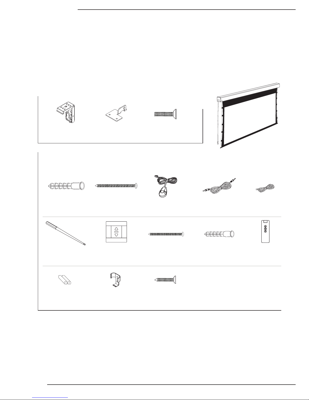
Mounting Bracket
Masonry Anchor
ø8mm x 40mm (8)
Mounting Bracket
Screw M5 x 42mm
(8)
External IR Receiver
18” Cable (1)
DC 12V Trigger
Cable 33’ (1)
RJ12 Control
Cable 10' (1)
Screen Adjustment
Tool (1)
Wall Switch (1) Wall Switch Mounting
Screw M4 x 30mm
(4)
Wall Switch Mounting
Anchor ø6mm x 30mm
(4)
IR Remote (1)
IR Remote
Battery AAA (2)
Remote Bracket (1) IR Remote Bracket
Mounting Screw
M3 x 15mm (2)
Wall Bracket A (2) Hanging Bracket A (2) Hanging Bracket
Screws M5 x 13mm
(5, includes 1 spare)
Projection Screen
(1)
2. Overview
3. Package Contents
Thank you for purchasing a Dragony™ Motorized Projection Screen. These projection screens can be hidden
away when not in use and are designed to be easy to operate and reliable.
They feature several convenient mounting methods, can be controlled manually or automatically by a control
system or projector, and are fully adjustable. The screen material includes a black, light-proof backing and
adjustable tension tabs along each side to keep the screen perfectly at during use. This screen is guaranteed to
provide years of maintenance-free operation and enjoyment.
DFM-TAB Installation Manual
Pg. 5
www.snapav.com Support: 866.838.5052
4. Pre-Installation
Before installing the projection screen, review this section thoroughly to be sure that no additional work is needed
to prepare the job for mounting and controlling the screen.
4.3. Powering the Screen
Operating Voltage: 120 Volts AC
Amperage: .85 Amps
The screen has a ve foot power cable permanently attached to the left side of the screen as seen from the
viewing area. Install or locate a receptacle close enough to plug the screen in prior to installation.
4.5. Control Method
Dragony motorized screens can be controlled via manual wall switch, IR remote, 12 volt trigger, or RS232.
Complete instructions for each method are described in the Control Setup section (Page 9). Decide on the
method that will be used before installation begins to avoid any issues with control later. Pre-wire any cables from
projectors or control systems prior to closing the walls or ceiling.
4.2. Unpacking the Projection Screen
As you unpack the projection screen:
• Remove all accessories from the box before
discarding any packaging. Use the Package Contents
section to verify that everything has been removed.
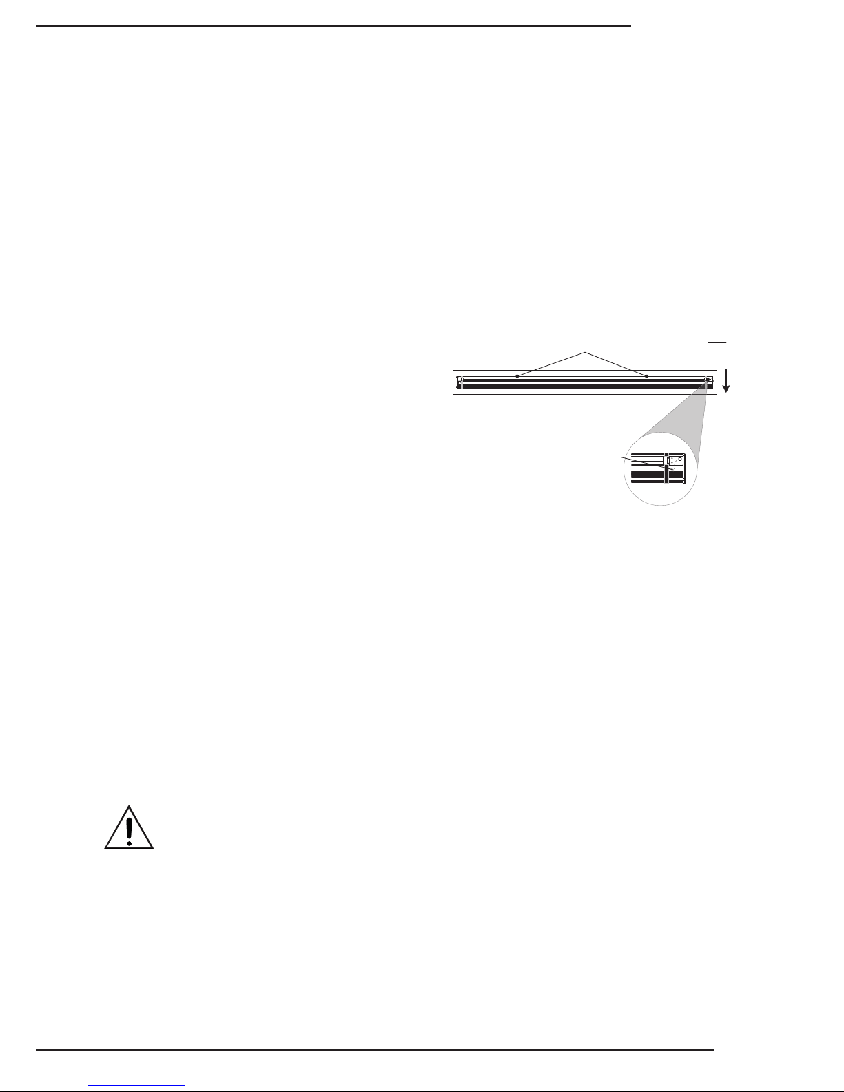
• After the screen is removed from the packaging, be
sure to remove the screws holding the bottom rail of
the screen in the housing.
• While unpacking and preparing the projection screen
for installation, take note of the location of the
adjustment screws and grommet as it may be difcult
to locate them after the screen is hung from the mounting brackets.
• Do not turn the adjustment screws until the screen is mounted and ready to be adjusted.
4.1. Required for Installation
Have an assistant help with installation to prevent damage or injury. The following tools will be needed to complete
the installation:
• Phillips Screwdriver
• 2 Step Ladders
• Electric or Cordless Drill
• Marker
• Level
• 7/32” Masonry Drill Bit to install 8mm concrete anchors
• 5/32” Drill Bit to install 6mm Wall Switch Screw anchors (optional)
4.4. Mounting Considerations
The design of the brackets allows for wall, ceiling, or hanging mounting. Plan the nal height of the screen’s
viewing surface prior to installation. Make sure there is enough room for the screen to hang freely below the
mounting location when extended.
Warning! The building structure and material in the mounting location must be capable of safely supporting
the weight of the projection screen. Included hardware is only meant for use with wood, surfaces with
wood bracing behind them, or concrete surfaces. Conrm with an engineer or contractor that the building
material will safely support the weight of the screen using the included mounting hardware.
Remove (2) Screws Holding Bar in Place
(Back of Housing)
Viewing
Area
Adjustment
Screws
Adjustment Screw
Grommet Location
Pg. 6
© 2013 Dragony
DFM-TAB Installation Manual
5. Installation
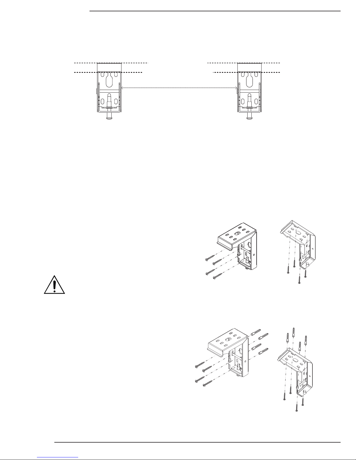
5.1.1. Mounting Brackets
Top of Screen Housing Will Be Here
Top of Brackets Must Be Level
Approximate Distance = Screen Housing Width Minus 8"
The mounting rail allows the mounting brackets to attach anywhere on the screen housing, but they should
be about 4” from each end to ensure that vibration or noise is prevented during operation.
1. Measure the width of the Projector Screen Housing (Dim. “B” in Section 12. Screen Dimensions and Weight)
and subtract 8” to estimate the distance the brackets should be mounted apart.
2. Mark the location of one bracket on the mounting surface, and measure over to the planned location of the
second bracket. Adjust the general location of each bracket to allow for both to mount securely to wood or
concrete. Be sure that wall-mounted brackets are level before installation.
3. Mark the screw holes for each bracket and install them:
Mounting to Wood Joists or Studs
Use the included mounting screws to secure the projector
mount brackets to the surface.
• No pre-drilling is necessary for most applications.
• Use 4 of the 8 included screws to mount each bracket
as pictured.
Mounting to Concrete Ceiling or Wall
Use the included anchors for the mounting holes and install
the screws into the anchors.
• Use a 7/32” masonry bit to drill a hole for each screw.
• Insert the anchors into the holes until they are ush.
• Do not install anchors into mortar joints.
• Use 4 of the 8 included screws to mount each bracket
as pictured.
Warning! If holes are pre-drilled, use no larger
than a 5/32” bit. Larger holes will not properly
grip the threads, and the projection screen
could fall.
Wall Mount
Wall Mount
Ceiling Mount
Ceiling Mount
5.1. Installing the Brackets
DFM-TAB Installation Manual
Pg. 7
www.snapav.com Support: 866.838.5052
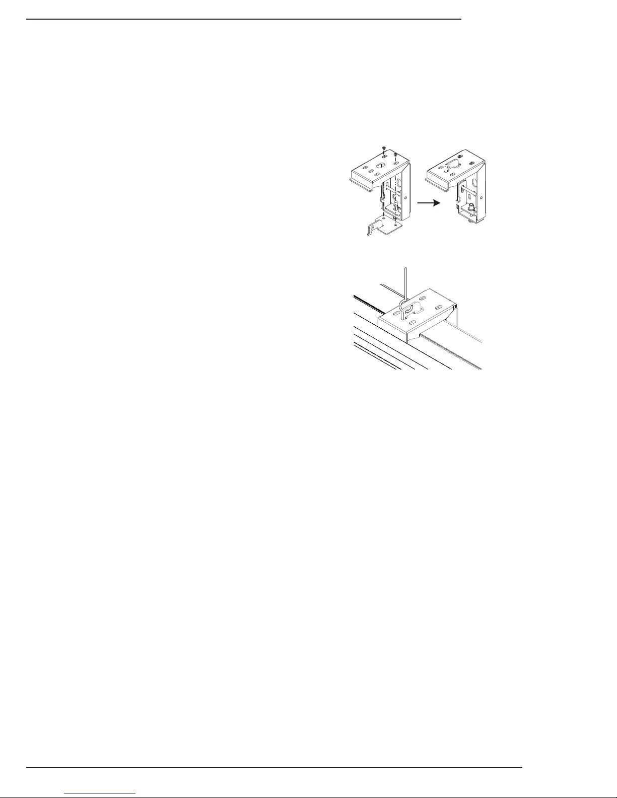
5.1.2. Hanging Mount
This screen includes optional adapters for converting the projector mounting brackets into hanging brackets. To
hang the projection screen, a suspension system (not included) must be installed and attached to the ceiling
structure that is rated for use in the location. Consult with local building code enforcement to determine the best
suspension method to use before installing the screen.
1. Install suspension system per manufacturer
instructions and local building codes.
2. Assemble each bracket according to the illustration.
Pull the adapter up through the bottom and insert
the screws from the top. Tighten the screws
securely.
a. For 123” and smaller models, there are three
screws to attach each adapter.
b. For 130” and above screens, there are two
screws to attach each adapter.
3. Hang one bracket from the suspension system at
the desired height.
4. Using a level, attach the second bracket to the
suspension system at the same height as the rst
bracket.
Hanger Adapter Assembly
Example of Bracket Installed
Pg. 8
© 2013 Dragony
DFM-TAB Installation Manual
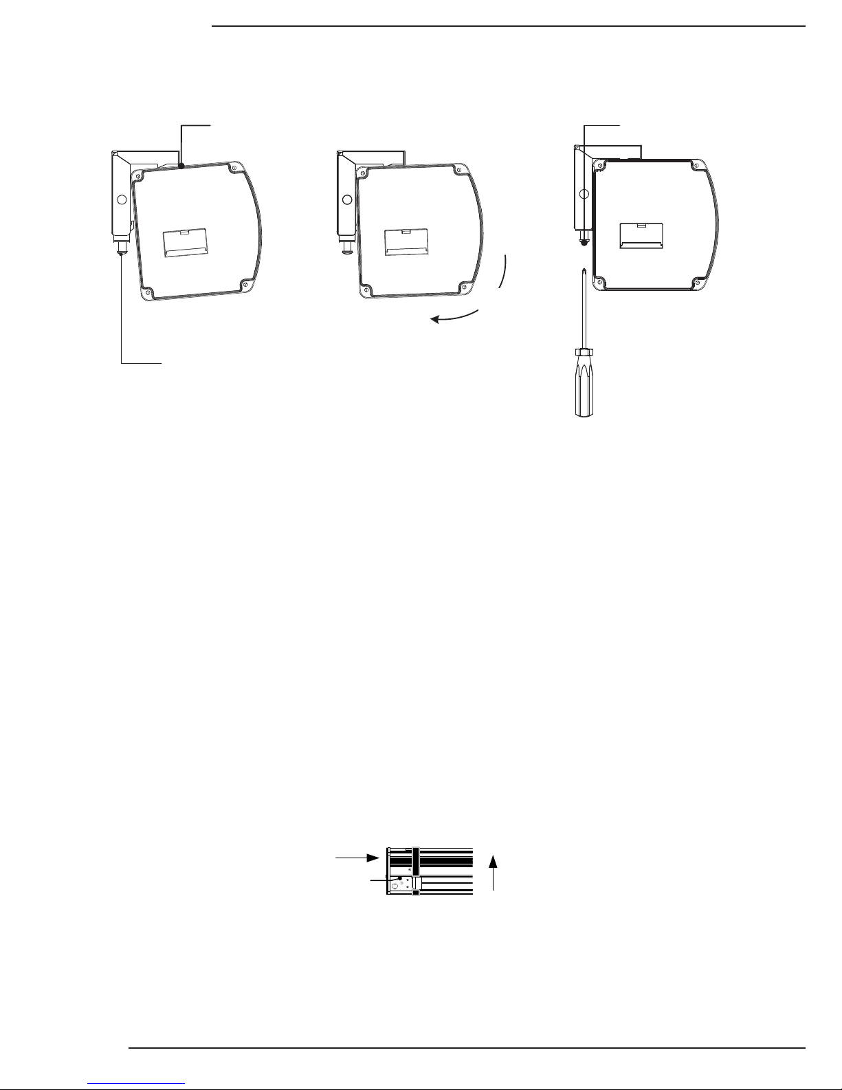
5.2. Installing the Screen on the Brackets
After the brackets are installed, have an assistant help lift and mount the projection screen.
5.3. Test the Screen
After the screen is secured to the mounting brackets, the unit can be tested. First, make sure the bottom bar of the
screen is moving freely in the housing. If the packing screws/tape were not removed prior to installation, they must
be removed before trying to move the screen position.
At the left bottom side of the screen housing, nd the manual test switch. Press the switch once and the screen
should begin moving. If nothing happens, make sure that 120 Volts AC is present at the plug being used.
Allow the screen to move down until it stops on its own, then press the button again. The screen should close
and stop with the bottom bar back in the original position. If everything is working correctly, continue with the
installation. For any issues see the Troubleshooting section on page 13.
Swing Housing In
Towards Bracket
Hang Lip On Edge
of Bracket
Tighten Lock Screw
To Secure Housing
Loosen Screws on Brackets
Before Attaching the Housing
1. Loosen the lock screw on the bottom of each bracket completely.
2. Set the screen on the brackets according to the diagram. The screen will hang from the brackets before they
are tightened.
3. Check the position of the screen and make any left or right adjustments as necessary.
4. Tighten the lock screws at the bottoms of the brackets and then check the screen housing using a level.
Make any adjustments necessary.
5. Leave any control wiring separate for the moment, and plug the power cord into a 120V AC outlet.
Viewing
Area
(Bottom View of Screen)
Control
Connections
Manual Power
Button
DFM-TAB Installation Manual
Pg. 9
www.snapav.com Support: 866.838.5052
6. Control Setup
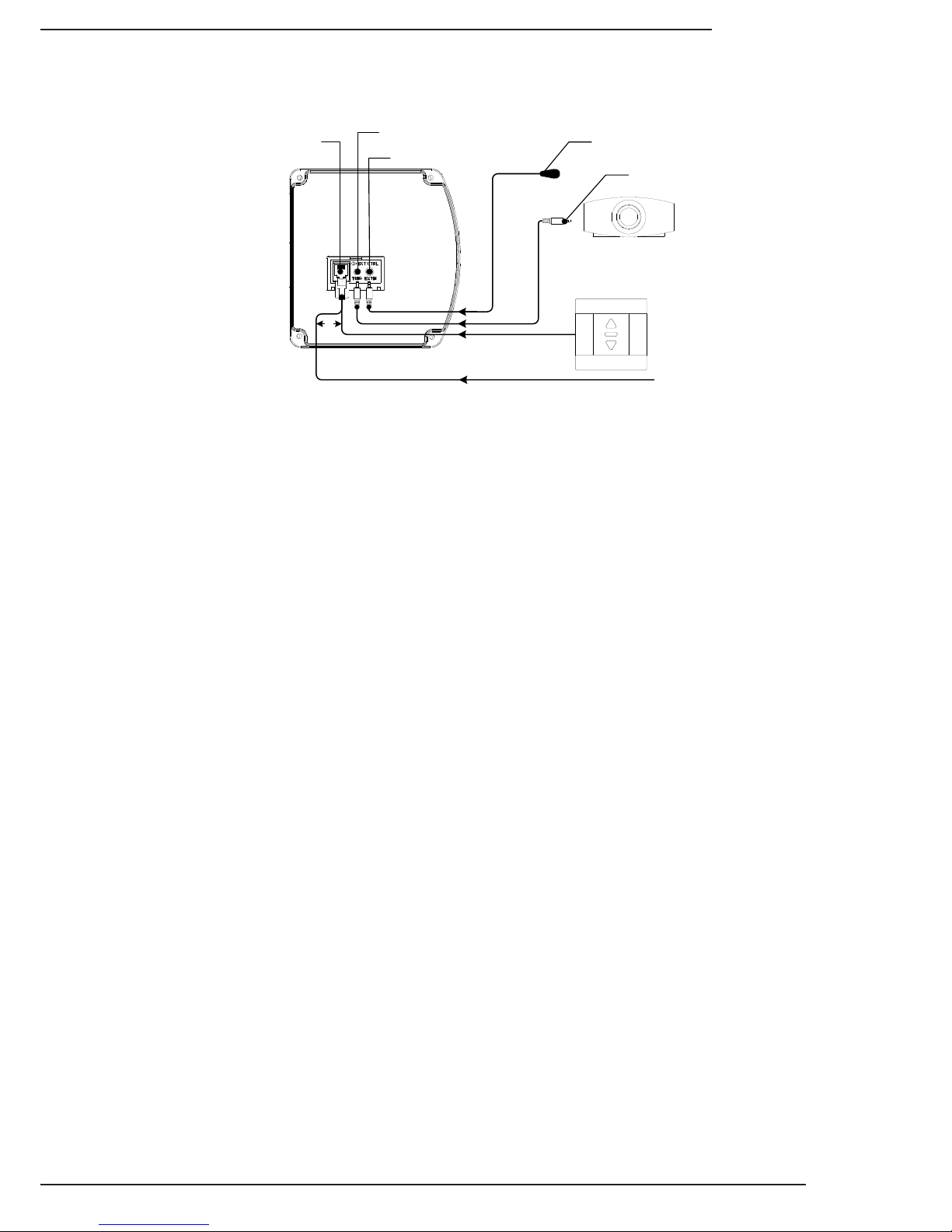
6.1. Control Wiring Diagram
or
EXT Control Connection
3 to 12V Trigger
IR Receiver
External IR Receiver
3.5mm Mono
for Remote Trigger
Wall Switch
(Wiring Diagram for EXT Control on next page)
From Control System
(RS232 or Contact
Closure)
6.2. IR Control (With Optional IR Receiver Extension)
The IR receiver built into the front of the screen works with remotes up to 26ft away at a maximum angle of 30°.
The included external IR receiver can be connected to the EXT IR port if additional range is needed.
To use the external receiver, plug it into the screen and have an assistant hold the receiver in different mounting
locations until the remote works reliably from where it will be used most. Mount the IR receiver using the adhesive
foam tape on the back.
Note: The included external IR receiver is proprietary to Dragony projection screens. Other IR receivers will not
work correctly.
6.3. 12 Volt DC Trigger Cable
Screens may be lowered and raised by 12 volt trigger signal sent from other equipment like a projector. A propri-
etary, 33ft cable is included for connecting a standard 1/8” (3.5mm) mono mini 12 volt trigger port to the TRIG port
of the projection screen.
12 volt trigger operates by sending a 3-12V DC signal to the screen when the projector turns on. The screen will
lower and remain lowered until the projector is turned off and the voltage drops to 0v (zero).
Other control methods may be used with 12V trigger. However, the screen will remain lowered for use if voltage is
present on the trigger while an attempt is made to close the screen.
Important! The projection screen still requires external AC power for operation. The 12 volt trigger connection will
NOT power the screen. Plug the AC power cord into a suitable outlet supplying 120V AC.
6.4. Manual Wall Switch
The included wall switch may be surface mounted near the projection screen for manual control. A 10ft RJ12 cable
is included to connect the switch to the screen. This cable may be replaced with a custom Cat5e/6 cable if longer
runs are required due to the location of the switch. See the next page for complete instructions.
6.5. RS232 Serial Control
Pins 1 and 2 on the EXT CTRL port may be connected to a control system serial output for one-way control.
Please see the DFM Motorized Screen Control Protocol for driver and command information, available on the Sup-
port tab at the DFM-NTT product page at www.SnapAV.com. The diagram illustrating the correct pins to use for
RS232 and instructions to extend the wiring from the screen to the control system are on the following page.
6.6. Contact Closure/Relay Control
The Dragony motorized screen may also be controlled via contact closure or relay control. Using the same
conductors that are used for the wall switch, momentarily short the Common wire to the Up, Down, or Stop
wire for the desired operation. The diagram illustrating the correct pins to use and instructions to extend the wiring
from the screen to the control system are on the following page.
Pg. 10
© 2013 Dragony
DFM-TAB Installation Manual
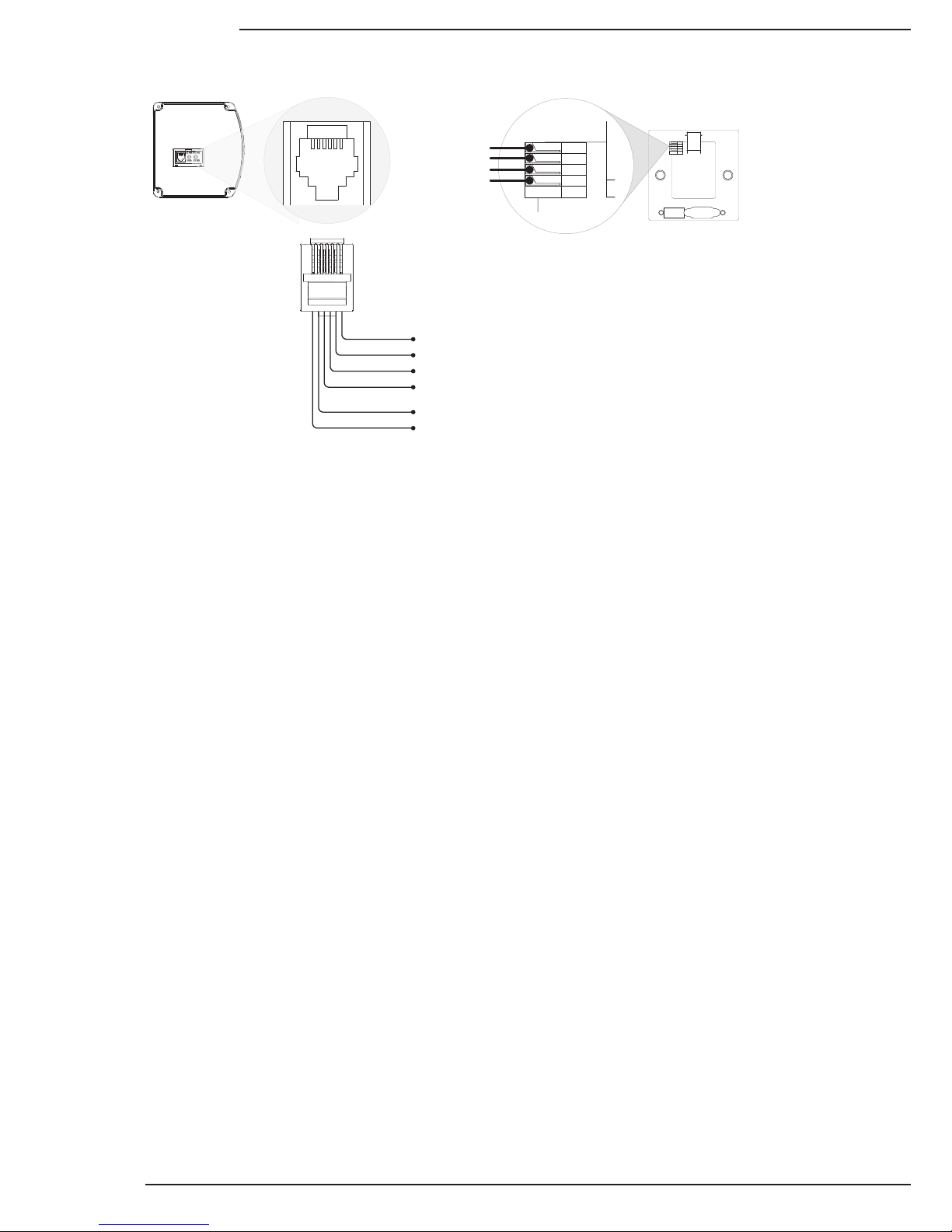
1 2 3 45 6
1 2 3 4 5 6
(Gold pins facing up) Back of Wall Switch
(RJ12 connector pointing up)
Pin6 - Up
Pin5 - Down
Pin4 - Stop
Pin3 - Common
Pin2 - RS232 Data Receive (RXD)
Pin1 - RS232 Data Transmit (TXD)
Up
Stop
Common
Down
Press-Fit 4-Wire
Connector
To wire for relay or contract
closure control, connect
conductors 3-6 to controller so
that Pin 3 (Common) is
momentarily connected to the
Up, Down, or Stop pin for the
desired operation.
6.7. EXT CTRL Port Wiring Diagram
6.8. Extending Control Wiring
6.8.1. Wall Switch
1. Run a Cat5e/6 cable from the projection screen EXT CTRL port to the switch location. Install the cable into the
wall at the switch location, and cut a 1” hole at the desired switch height. Pull about 6” of cable out of the hole
for attachment to the wall switch.
2. Remove the knockout from the switch back-box and mount it over the cable with the RJ12 port opening pointing
down. Use the supplied screws and anchors to secure it to the wall.
3. Cut the RJ12 control cable. Leave about 12” of cable attached to the connector. Splice four of the Cat5e/6
conductors to the appropriate wires as shown above at the projection screen. Then, plug the RJ12 into the EXT
CTRL port. Insulate the ends of the unused RJ12 conductors 1 and 2 to prevent short circuits.
4. Strip the insulation from each of the four conductors used in the Cat5e/6 cable about ¼”. Locate the press-t
connector on the switch assembly and terminate the conductors as shown above. Make sure to match the pin-
out correctly between the screen and the wall switch.
5. Mount the wall switch to the back-box so that the up and down buttons face the right directions.
6.8.2. Contact Closure or RS232 Control
1. Run a Cat5e/6 cable from the control system processor location to the projection screen.
2. Cut the RJ12 cable and leave about 12” of cable attached to the connector.
3. Terminate conductors in the Cat5e/6 to the desired pins of the RJ12 connector as shown in the diagram above.
Insulate the ends of the unused RJ12 conductors to prevent short circuits.
4. Terminate the same conductors to the appropriate wires on the RS232 port or contact/relay connection of the
control system processor.
Tabla de contenidos


