
Smaak HOOK Manual de usuario

HOOK
OWNER’S MANUAL


2
Owner’s manual
Contents
1. GENERAL............................................................................................................................... 5
1.1. Revisions........................................................................................................................ 5
1.2. Warnings ........................................................................................................................ 5
1.3. Waste management ....................................................................................................... 6
1.4. Authorized technician..................................................................................................... 6
2. SPECIFICATIONS AND INSTALLATION................................................................................ 7
2.1. Dimensions..................................................................................................................... 7
2.2. Certifications................................................................................................................... 7
2.3. Electrical specifications .................................................................................................. 7
2.4. Specifications ................................................................................................................. 8
2.5. Components identification .............................................................................................. 8
2.6. Options........................................................................................................................... 9
3. OPERATING INSTRUCTIONS ............................................................................................. 10
3.1. Optimal use .................................................................................................................. 10
3.2. Working principles........................................................................................................ 10
3.3. Product layout in the vacuum chamber ........................................................................ 11
3.3.1. Solids of minimal thickness.................................................................................... 11
3.3.2. Solids of medium thickness (from 1 to 3 in / 25 to 75 mm) .................................... 11
3.3.3. Solids of higher thickness (from 3 to 6 in / 75 to 150 mm) ..................................... 11
3.3.4. Liquids or solids with liquids................................................................................... 12
3.3.1. Gas injection nozzles............................................................................................. 12
3.4. Product particularities................................................................................................... 13
3.4.1. Suggestions........................................................................................................... 13
3.4.2. Packaging liquids................................................................................................... 13
3.4.1. Products to avoid and products that require special treatment .............................. 14
3.5. Vacuum packing........................................................................................................... 15
3.5.1. Packing sequence.................................................................................................. 15
3.5.2. Basics .................................................................................................................... 16
3.5.3. Function mode....................................................................................................... 17
3.5.3.1. Program creation............................................................................................. 17
3.5.3.2. Program deletion............................................................................................. 17

3
Owner’s manual
3.5.4. Programming mode ............................................................................................... 17
3.5.4.1. Program identification...................................................................................... 17
3.5.4.2. Vacuum level by sensor .................................................................................. 18
3.5.4.3. Vacuum plus.................................................................................................... 19
3.5.4.1. Vacuum sensor controlled gas injection.......................................................... 19
3.5.4.2. Sealing time..................................................................................................... 19
3.5.5. Running a vacuum cycle........................................................................................ 20
3.5.6. Diagnostic menu.................................................................................................... 20
3.5.7. Menus structure..................................................................................................... 21
3.5.7.1. Function mode................................................................................................. 21
3.5.7.2. Programming mode......................................................................................... 21
3.5.7.3. Diagnostic menu.............................................................................................. 21
3.6. Return to atmospheric pressure speed adjustment (soft air)........................................ 21
4. DAILY MAINTENANCE......................................................................................................... 23
4.1. Cleaning....................................................................................................................... 23
4.2. Verifications.................................................................................................................. 23
5. TROUBLESHOOTING .......................................................................................................... 24
6. MAINTENANCE.................................................................................................................... 27
6.1. Maintenance schedule.................................................................................................. 27
6.2. Vacuum pump .............................................................................................................. 28
6.2.1. Parts identification.................................................................................................. 28
6.2.2. Oil change.............................................................................................................. 28
6.2.2.1. Draining the oil ................................................................................................ 28
6.2.2.2. Filling up the vacuum pump............................................................................. 29
6.2.3. Replacing the exhaust air filter............................................................................... 29
6.3. Seal bars ...................................................................................................................... 30
6.3.1. Parts identification.................................................................................................. 30
6.3.2. Replacing the Teflon™ tape................................................................................... 31
6.3.3. Replacing the elements ......................................................................................... 31
7. SALES CONDITIONS AND WARRANTY ............................................................................. 33
8. APPENDIX................................................................................................................................i
8.1. Electrical schematics........................................................................................................i
8.2. Pneumatical schematics..................................................................................................v


5
Owner’s manual
1.GENERAL
1.1. Revisions
Revision
Date
Modifications
0
14-05-2020
Original manual
1.2. Warnings
This symbol points out important safety
instructions which, if not followed, could
endanger the personal safety and/or
property of yourself and others. Read and
follow all instructions in this manual before
attempting to operate your appliance.
Failure to comply with these instructions
may result in personal injury.
• Read, understand, and follow all
instructions in the manual and on the oven
before starting. Keep this manual in a safe
place for further and regular reference and
for ordering replacement parts.
•Only allow responsible individuals familiar
with the instructions to operate the
appliance. Be sure to know the controls
and how to stop the appliance quickly.
• Never put your hands near moving parts.
• Only allow qualified individuals to perform
maintenance of your appliance.
• Remove all obstacles, which may interfere
with the appliance functions.
• Clear the work area of any potential
source of danger such as electrical wires,
buckets, knives, etc.
• Make sure that everyone else is clear of
your work area before operating the
appliance.
• Do not sit or stand on the appliance.
• Always turn off the appliance after your
work is done. Never leave a running your
appliance unattended.
• Always disconnect the appliance before
attempting any maintenance.
• Do not wear loose-fitting clothes or jewelry
as they may get caught in moving parts of
the appliance.
• Always wear appropriate shoes, to prevent
injury.
• Work only in daylight or good artificial
light.
• Do not operate this appliance while under
the influence of alcohol or drugs.

6
Owner’s manual
1.3. Waste management
• Use proper containers when draining the
oil. Do not use food or beverage
containers that may mislead someone into
drinking from them. Properly dispose of
the containers, or store them in a safe
place immediately after draining the oil.
• Prior to disposal, determine the proper
method to dispose of waste from your
local office of Environmental Protection
Agency. Recycling centers are established
to properly dispose of materials in an
environmentally safe fashion.
1.4. Authorized technician
WARNING
All installation and/or service on this appliance must be performed by qualified, certified,
licensed and/or authorized installations or technical service personnel. All electrical, gas and
plumbing connections must be made by authorized technicians and in compliance with all
electrical, gas, plumbing and safety requirements.
It is possible to obtain these services by contacting customer service, a sales representative or
a local service agency.
DEFINITIONS
QUALIFIED INSTALLATION PERSONNEL
Qualified installation personnel can be represented by an individual, a firm, a corporation or a
company which, either in person or through a representative, is involved and is responsible for:
1. The installation of electrical wiring from the electric meter, main control box or service outlet
to the electric appliance. The qualified installation technician must be experienced in such
work, be familiar with all required precautions, and have complied with all requirements of
state or local authorities having jurisdiction.
2. The appliance, when installed, must be electrically grounded in accordance with local
codes, or in the absence of local codes, with the National Electrical code ANSI/NFPA 70, or
the Canadian Electrical code, CSA 22.1 No 109 or conform to UL STD 197.

7
Owner’s manual
2.SPECIFICATIONS AND INSTALLATION
2.1. Dimensions
Hauteur
Depth
Width
Package (wood)
25" (635 mm)
32" (815 mm)
29" (740 mm)
Appliance
23" (585 mm)
23.7" (600 mm)
19.7" (500 mm)
Chamber height
6.8" (175 mm)
Distance between
seal bars
13.1" (335 mm)
Seal bars length
19.1" (485 mm)
2.2. Certifications
ETL listed C & US
Conforms to UL STD 73
Certified to CAN/CSA C22.2 No. 68
ETL Sanitation Listed
Conforms to NSF/ANSI STD 169
2.3. Electrical specifications
Voltage: 120 V / 1Φ / 60 Hz
Current: 15 A
Pump: 8 m³ / 0.35 kW
This appliance requires a dedicated power outlet and circuit. Usage of extension
cords are strongly not recommended and should be of gauge 10 AWG or larger
(Heavy Duty). Usage of an undersized extension cord can cause serious damage
to the vacuum pump of the appliance.

8
Owner’s manual
2.4. Specifications
- Built in stainless steel with clear lid
- Pouch cut-off
- Soft-air that allow a slow return to atmospheric pressure
- 8m³ pump
- Microprocessor
- Precision vacuum sensor
- Shims to adjust product height
- Silencer that reduce noise when returning at atmospheric pressure
- Gas injection system (Modified Atmosphere Packaging) (20% Maximum oxygen)
2.5. Components identification
1- Clear lid
2- Stainless steel frame
3- Lid retention clip (Only used to keep the lid down when in storage, DO NOT USE
while the appliance is operating)
4- Seal bars (Lower seal bar not visible on the picture)
5- Lid seal
6- Removable shims for the product packaging
7- Microprocessor
8- Legs
4
5
3
6
2
7
8
4
4
1
4
9
Owner’s manual
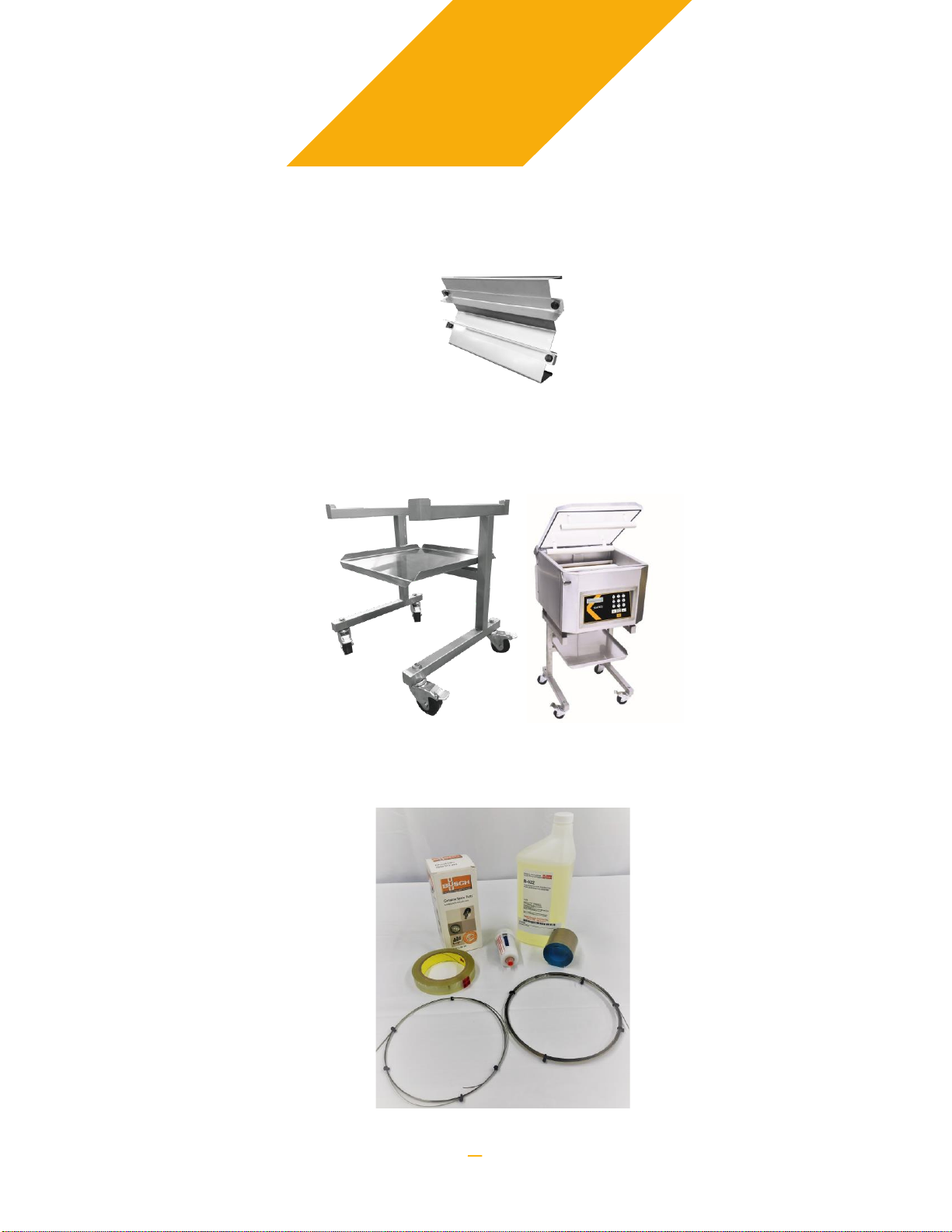
2.6. Options
1- Inclined shim HOOK FILLER: Allow to place the product in the optimal angle every
time, ideal for liquids.
Product code: SMAAK_HOOK_FILLER
2- HOOK CART: Allow you to easily carry your appliance around while offering a work
area at the ideal height.
Product code: SMAAK_HOOK_CART
3- HOOK MAINTENANCE KIT: Everything you need to perform preventive maintenance
on your appliance.
Product code: SMAAK_HOOK_MK
Tabla de contenidos
Otros manuales de Electrodoméstico de cocina de Smaak


