SlatPro SLAG HOG 67123 SH3G Manual de usuario

User Manual
67123 SH3G
Slag Removal Tool for use on laser cutting machines with
minimum 1.75” between slats
Slatpro LLC
4757 Mustang Circle
Mounds View, MN USA
Phone: +1 763-452-4550
Fax: +1 763-452-4560
www.slatpro.com

1. Safety
1.1 General Safety Instructions
ΔWARNING! Read all safety warnings and all instructions. Failure to follow the warnings and
instructions may result in electric shock, fire and/or serious injury.
Save all warnings and instructions for future reference.
1.2 Slaghog Specific Safety Warnings and Instructions
A. Unplug tool from power before performing maintenance on Slaghog
B. Use protective equipment. Always wear safety glasses when working with the machine.
Protective clothing is recommended such as dust mask, gloves, steel toed non-slip footwear
and hearing protection.
C. Do not expose tool to wet conditions or operate in damp environment
D. Power cord to be kept clear from working range of machine. Always lead cord away from
machine. Do not apply tension to power cord.
E. Switch tool off immediately if it stalls. Lift cutters out of slats before restarting.
2. Supporting Information
2.1 Conditions of use
The tool is only to be use for removing the slag from slats on laser cutting machines where the slats
create a horizontal plane and the vertical slat sides are cleaned. The slats may be steel, stainless
steel or copper. Not to be used in wet areas or outside.
WARNING
2.2 Mains Connection
Connect only to single-phase AC voltage as indicated on the rating sticker. Plug-in receptacle to
have ground contact with current capacity exceeding the tools rating.
Only plug in when tool switches are off.
2.3 Maintenance
The ventilation slots must be kept clear or over-heating may result.

If the supply cord is damaged it must only be replaced by qualified personnel. Only use SlatPro
replacement parts when performing repairs or maintenance.
2.4 Technical Information
TechnicalData
SlagHogSlagRemovalTool
Productioncode 67123‐120V 67123‐230V
Voltage 120Va.c. 230Va.c.
Current 10amps 6amps
Frequency 50/60hz
Weight 47lb 21.4kg
NoiseInformation
MeasuredvaluesdeterminedaccordingtoEN60745.Typically,theA
weightednoiselevelsofthetoolare:
Soundpressurelevel(UncertaintyK=3db(A)) 90db(A)
Soundpowerlevel(UncertaintyK=3db(A)) 101db(A)
WearearProtectors!
Vibrationinformation
Vibrationtotalvalues(triaxialvectorsum)determinedaccordingto
EN60745
Connectonlytoasingle‐phaseACcurrentsupplyandonlytomains
voltagespecifiedontheratingplate
Vibrationemissionvalueah,d 4.3m/s2
UncertaintyK= 1,5m/s2
Warning
The Vibration emission level given in this information sheet has been measured in accordance with a
standardized test given in EN 60745 and may be used to compare one tool with another. It may be used for a
preliminary assessment of exposure.
The declared vibration emission level represents the main applications of the tool. However, if the tool is used for
different applications, with different accessories or poorly maintained, the vibration emission may differ. This may
significantly increase the exposure level over the working period.
An estimation of level of exposure to vibration should also take into account the times when the tool is switched
off or when it is running but not actually doing the job. This may significantly reduce the exposure level over the
total working period.
Identify additional safety measures to protect the operator from the effects of vibrations such as: maintain the tool
and the accessories, keep the hands warm, organization of work patterns.

2.5 Symbols
Caution! Warning! Danger!
Always disconnect the plug from the socket before carrying out
any instructions
Please read the instructions carefully before starting the
machine.
Tool uses protective earth and must be plugged into grounded
outlet
3. Description
The tool is moved along the slats on the bed of a laser machine to remove slag that accumulates while
cutting. Rotary cutting tools ride on each side of the slat to lift and remove the slag. It may be used on
steel, copper or hybrid steel/copper slats. When not in use it may be rolled along the floor and stored in
the upright position.
4. Initial Assembly
The Slag Hog ships in two pieces; power unit and the handle assembly. All fasteners are metric.
Remove the nuts and button head socket screw from the 1.36” diameter stub on the power
unit.
Slide the handle on the stub with the power out cord of the handle on the same side as the
plug in on the power unit.
Plug the power cord from handle tube into the power unit
WARNING
Do not plug into power outlet before verifying the switches on the handle and power unit are
off; both rocker switches to 0.
5. Operation
The tool must be plugged into a receptacle with a grounded outlet
Before plugging into power verify that the two switches are turned off
Wear work gloves and safety glasses when operating
Lift onto the cutting machine bed with care
WARNING Use extreme care near the cutters. Do not touch them unless the tool is unplugged.

The tool has two on/off switches
Figure 1
Figure 2
Rocker switch on handle end, in off position,
acts as circuit breaker reset in case of over-
current
Rocker Switch on motor enclosure in off
position.
Both switches must be in ON or “l” position to run. Turning either switch OFF (“0” position) stops motor
operation.
The upper left picture shows the on/off switch that acts as the circuit breaker when the unit is overworked.
If the slats are not straight it is possible for the cutters to grab onto two slats and stall the motor which will
trip the breaker. If this occurs wait a minute, reset the breaker switch, and resume operation. When slats
have excess slag build up it may cause the circuit breaker to overload. If this happens the operator will
need to reduce force used for cleaning slats. If this occurs, reset the breaker, and resume operation.
To begin use, place the tool on the slat bed of the laser machine, center the cutters over a slat, and turn
on both switches. Cutter rotation will pull the tool down on the slats. The slats can be cleaned by moving
the tool in either direction along the slat.
Figure 3
With switches off, plug tool into a power outlet with appropriate current capacity to accept value given on
machine label or as shown above in the Technical Data table.

Figure 4
Cutters shown centered on slat
To see the unit in operation, go to Youtube and search for Slaghog. The best video is:
https://www.youtube.com/watch?v=PDvEFRREdgg
The cutter geometry is ideal for most slat/pallet bed configurations. If the fit of the cutters on the slats
does not seem correct contact the factory to find out options that are available.
When storing in upright position the unit is unstable and care must be taken to ensure that it does not fall
over, which may lead to damage of handle end components. Damage due to dropping, improper
handling, or falling over is not covered by warranty.
6. Maintenance
WARNING Disconnect power by unplugging from outlet before performing any work on the
tool
6.1 Cutters
The cutters will wear over time and require replacement.
Tools required for replacement
6mm L hex wrench
6mm male hex socket wrench
Adjustable open wrench
Replacement Cutters
66106 – 14ga Slats
66031 – 11-12ga Slats
66105 – 10ga Slats
66095 – 7ga Slats
66096 – .250” Slats
67067 – .11/12ga Deep Slats
Parts required are RH & LH Cutter Set with cap screws. The most common cutters are 66031 SET
for 11/12ga slats. Most replacement cutters come with two M8 x 22 cap screws, two washers, and
Blue Loctite 242. 67067 Cutter is longer and uses a M8 x 70 cap screw.
Place the tool on its back with the cutters up.
Place the wrenches as shown and remove the right cutter cap screw with counterclockwise rotation.
Remove the right cutter. The cutter may be tight on the shaft and will require light tapping with a
hammer to remove.
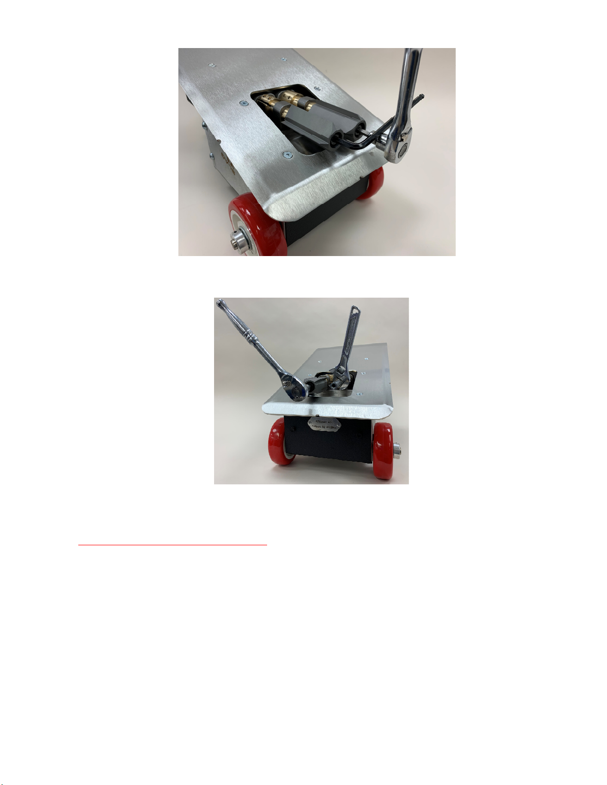
Figure 5
Place adjustable wrench on flats of right shaft and remove left cutter with counterclockwise rotation.
Figure 6
Slide the new right hand and the left-hand cutters so that the flats between the shaft are facing the
base plate as shown. The cutters rotate so that the slag chips are pulled up toward the base plate.
The cutters must be installed as shown.

Figure 7
Apply Loctite 242 to the cap screw threads. With washers in place, thread then tighten cap screws into
shaft ends using the male hex socket wrench and L hex wrench approach.
Cutter Wear
Even though cutters are made from hardened tool steel they do wear and will need to be replaced.
When slag removal gets worse it may be time to replace cutters. The best way to determine if they are
worn is to measure the distance between cutter tips. The below picture shows the proper gap for new
11-gauge cutters.
Figure 8 Measuring Cutter Gap
Slat Max
gauge Thick(inch) Gap
14 0.074 0.124
12 0.104 0.154
11 0.119 0.169
10 0.135 0.185
7 0.179 0.229
Table 1 Max Gap for Cutter Replacement
When the gap has increased by .050 it is time to replace cutters.
Other Wear
If the measured gap is less than the slat thickness, the Cutter Support Plates may have worn from
hammering action after repeated use. This condition will overwork the motor and cause short brush life
and may damage the motor. Call SlatPro for further advice on this problem.
Flat side of cutters towards base
p
late

6.2 Motor Brushes
If the tool has less torque while in use, it is likely that the brushes need replacement.
Parts Required: Qty 1 of 67179SET Brush Kit for SH3
There are access holes to brushes in top and bottom of Motor Enclosure
Unthread and remove Brush Caps from motor
Remove old brushes and install new and thread caps back in place
6.3 Other maintenance
All other repairs require qualified personnel to perform. In this case, the factory or distributor should
be contacted for further instructions.

SlaghogTroubleshootingGuide
Problem ProbableCause Solution
Ifmeasuredgapissmallerthanslatthickness,sendunitinfora
rebuild/repair.Thiscouldmeanthatcuttersupportplatesare
wornortherehasbeenabearingfailure.
Ifthegapistoobig,replacethecutters.
Cuttersareinstalled
incorectly.Seefigure7
Checktoseeifthecuttersmayhavebeeninstalledbackwards.
Installthecutterscorrectly.
Theswitchinthehandleend
boxhasfailed.
Replacetheswitch.Seepartslistforpropperpartnumber.
Theswitchinthemotor
enclosurehasfailed.
Ifyoureplacetheswitchinthehandleendboxandtheunitisstill
notstarting,replacetheswitchontopofmotorenclosure.
Issuewithwiring.
Refertorepairmanual,verifyallwiresareproperlyconnected.
Checktoseeifbrusheshaveworn.Ifworn,replacebrushes.
Ifbrushesarenotworn,replacethemotor.
Checktoseeifbrusheshaveworn.Ifworn,replacebrushes.
Ifbrushesarenotworn,replacethemotor.
Burningsmell
andsparks
comingfrom
insidemotor
enclosure
Motorhasmalfunctioned. Replacethemotor.
Grinding
soundwhile
running,or
cuttersnot
rotating
Brokengearsingearhousing Checkandreplacegearsandmotor.
Motorhasmalfunctionedor
brushesareworn.
Sparksare
comingfrom
insidemotor
l
Themachineis
notstarting.
Motorhasmalfunctioned
Cuttergapistoolargeortoo
small.SeeFigure8andMax
gaptable.
Themachineis
notcleaning
well.
Tabla de contenidos
Otros manuales de Herramientas de SlatPro


