GENERAL DISCUSSION followingmanner. CarrierisgeneratedbyQ3 CarrierOscil-
lator, whichisa Pierceoscillatorwith the crystaloperating
in parallelresonance.Thisstageoperatesin both thetrans-
mit andreceivemodes. Whentransmitting,theRF output
of the oscillator is injected into the control grid of the
BalancedModulator,VI3. This b'alancedmodulatoris a
beamdeflectiontube,andoperatessimilarto acathoderay
tubein thatthe electronbeamfrom thecathodeis deflected
to oneoutputplate orthe other by thechargeappearingon
the deflectionplates. The carriersignalfed to the control
grid of the balancedmodulator appearson both platesof
the output. The two platesareconnectedto Transformer
T130I. The deflectionplate DCvoltagesareadjustedby
meansof thecarrierbalancecontrol, RI30S, sothatthe RF
beingfed to the output plateswill cancelout, andtheout-
put fromTl.301 will bezero. Audio signalsfrom theMicro-
phoneAmplifier, VI4, areappliedasamodulatingvoltage
to one deflectionplate, and the two sidebandsresulting
from the sumanddifferencefrequenciesof the audio and
carriersignalsappearin the output of transformerTI30I.
Carriersuppressionis approximately 60 db down. The
Carrier Insertioncontrol limits the amountof carrierthat
~ beinsertedin AMand thus protectsthefinal amplifier
from beingoverdriven.
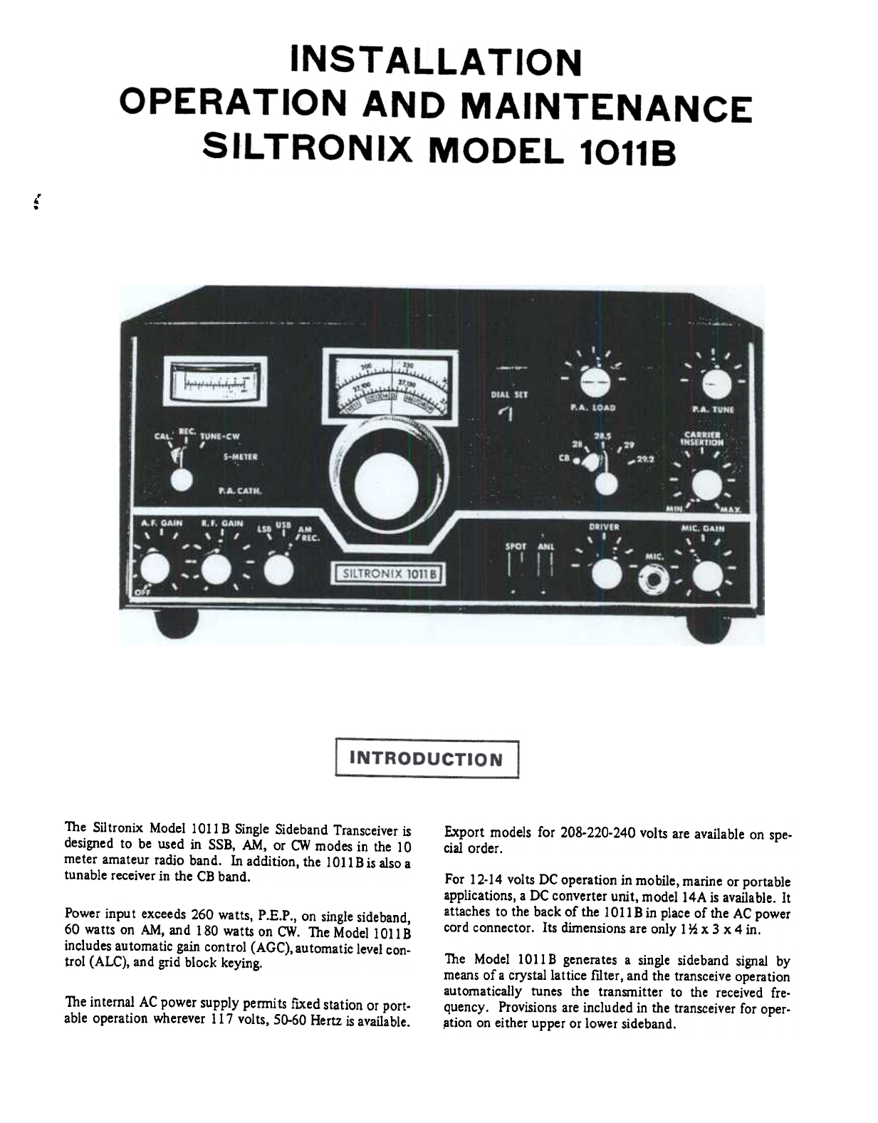
The Siltronix 1011B transceiverprovidessinglesideband,
suppressedcarriertransceiveoperation,and generatesthe
singlesidebandsignalbymeansof acrystallattice filter. To
permit a logical discussionof this mode of operation,cer-
taindefinitionsarenecessary.
h1 a normal AM signal(doublesidebandwith carrier),a
radiofrequencysignalismodulatedwith anaudiofrequency
signal. This is consideredby manyto be merelya caseof
varying the amplitude of the carrierat an audiorate. hi
fact, however,thereare actuallysideoandfrequenciesgen-
erated,whicharethe resultsof mixingtheRFandtheA.F.
signals. Thesesidebandsarethesumof, andthe difference
between,the two heterodynedsignals. In the detection()f-
this conventional AM signal,the two sidebandsaremixed
with the carrierto recoverandreproducethe audiointelli-
gence. Thisis aninefficientmeansof transmission,because
only 25 percentof the transmittedpoweris usedto trans-
mit intelligence. Thereareotherattendantdrawbacksalso.
The bandwidthof AMvoice transmissionis approximately
6 KHz,whiletheactualdemodulatedaudioisonlyapproxi-
mately 3 KHz. The result is inefficient useof the fre-
quencyband,and overhaIf of theallottedbandisunusable
dueto heterodynes,interference,andcongestion.. Thedoublesideband,suppressedcarriersignalis thencou-
pled from the secondarywinding of Tl30l to the crystal
filter, which suppressesthe lower sideband,and permits
only the uppersidebandto befedto the First IF Amplifier
V7. The carrier frequencyis generatedat approximately
5500.0KHz, nonnal sideband.Withtheoppositesideband
crystal, the carrier crystal frequencywill be 5504.6 KHz,
and this positionsthe doublesidebandsignalonthe other
sideof the filter responsecurve,attenuatingthetIpperside-
bandby atleast50db.
h1 the single sideband,suppressedcarriermode of trans-
mission,only one of the sidebandsignalsis transmitted.
The othersidebandand the carrieraresuppressedto negli-
giblelevel. h1addition to increasingthe transmissioneffi-.
ciency by a factor of four, single sidebandeffectively
doublesthe numberof stationsor channelswhichcanbe
usedinagivenbandof frequencies.
It should be rememberedthat in the singlesideband,sup-
pressedcarrier mode of transmitting,theunwantedside-
bandand carrier are only suppressed,not entirelyelimin-
ated. Thus, with a transmittedsignalfrom a transmitter
with 50 db sidebandsuppression,the other or unwanted
sidebandwill be present,and will be transmitted,but its
levelwill be 50 db belowthe wantedsideband. Whenthis
signalis receivedat a levelof 20dbover59,theunwanted
sidebandwill be presentat a level of approximately55.
The sameis true of carriersuppression.With carriersup-
pressionof 60 db,and asignallevelof 20 dbover59,car-
rier will be presentat a levelof approximatelyS3to S4.
Q1, the VFO 2N706 Oscillator,operatesin the common
baseconfigurationasaColpittsoscillator. Q2,the buffer,is
usedfor isolation. Theextremelygoodregulationachieved
throughusingthe Zenerdiode regulatorD1712acrossthe
biassupplyvoltage,alsocontributesto thestability.
TheVFO in the ModellOllB exmbitsextremelygoodsta-
bility after the initial wann-upperiod. Drift from a cold
start will belessthan 2 KHz duringthe flIst hour. After
theinitial wann-upperiod,drift will benegligible.
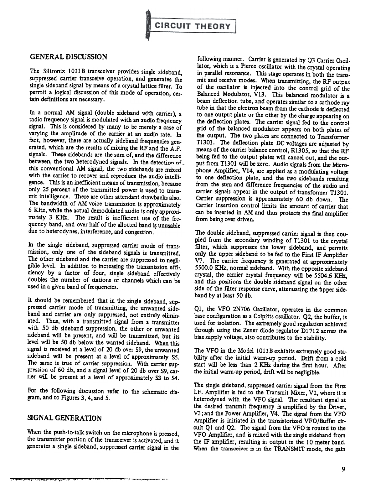
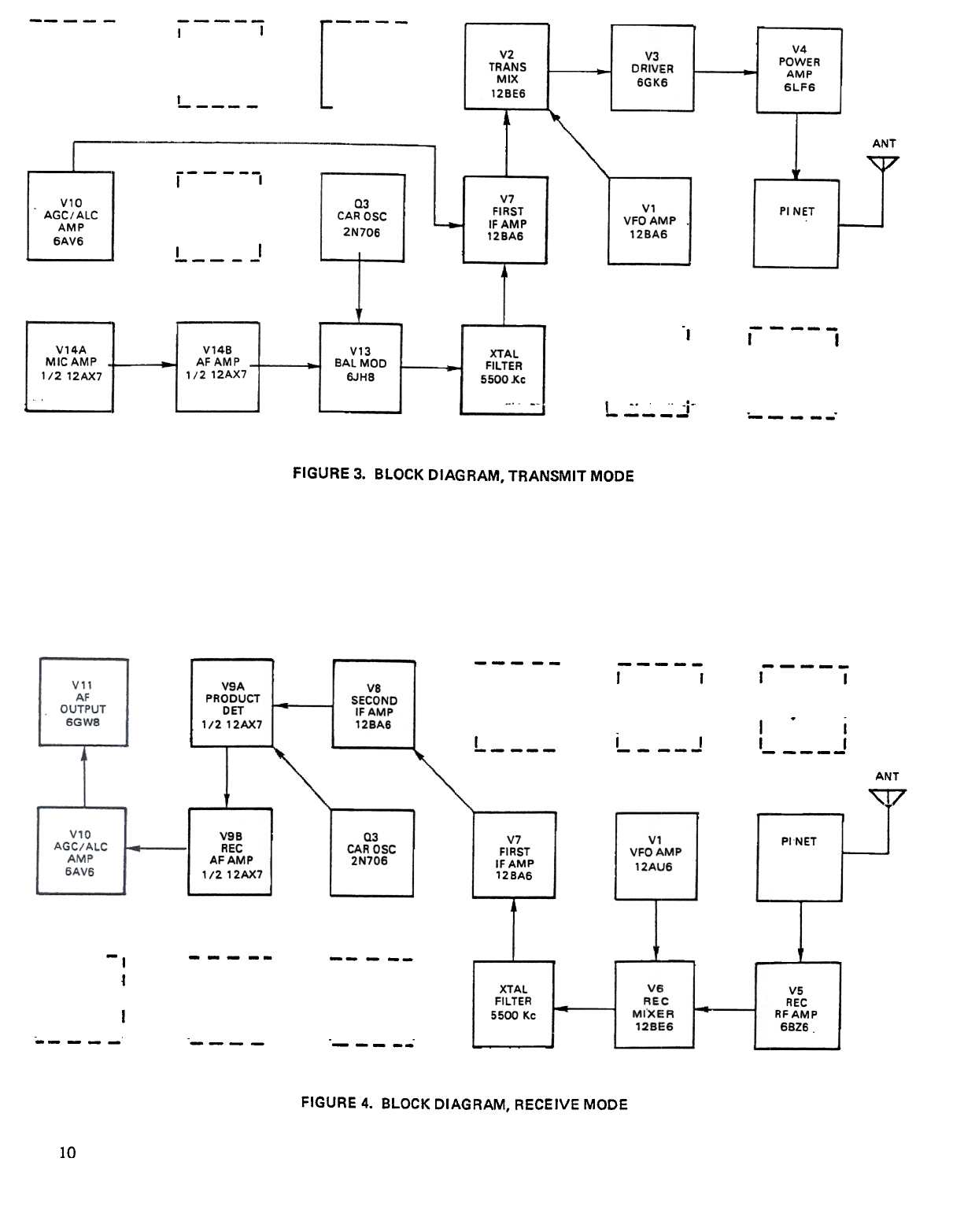
Thesinglesideband,suppressedcarriersignalfrom the First
I.F. Amplifier isfed to the TransmitMixer,V2, whereit is
heterodynedwith the VFO signal. The resultantsignalat
the desiredtransmit frequencyisamplified by the Driver,
V3;andthePowerAmplifier,V4. Thesignalfrom theVFO
Amplifier is initiated in the transistorizedVFO/Buffer cir-
cuit QI andQ2. Thesignalfrom theVFOisroutedto the
VFO Amplifier,and ismixed with thesinglesidebandfrom
the IF amplifier,resultingin output in the 10 meterband.
Whenthe transceiveris in the TRANSMITmode,the gain
For the following discussionrefer to the schematicdia.
gram,andto Figures3,4, and5.
SIGNAL GENERATION
Whenthe push-to-talk switch on the microphone is pressed,
the transmitter portion of the transceiveris activated, and it
generatesa single sideband,suppressedcarrier signal in the
9
'. "-.j .., ,. .,-,,., ,