SIEB & MEYER CNC 8.00 Series Manual

CNC 8x.00
Demo Kit
Installation and Setup
P-TD-0000431.2
2015-11-05
SIEB & MEYER W

Copyright
Translation of the original instructions, Copyright © 2015 SIEB & MEYER AG
All rights reserved.
This manual or extracts thereof may only be copied with the explicit authorization of
SIEB & MEYER AG.
Trademarks
All product, font and company names mentioned in this manual may be trademarks or registered
trademarks of their respective companies.
SIEB & MEYER worldwide
For questions regarding our products and technical problems please contact us.
SIEB & MEYER AG
Auf dem Schmaarkamp 21
21339 Lüneburg
Germany
Phone: +49 4131 203 0
Fax: +49 4131 203 2000
http://www.sieb-meyer.de
SIEB & MEYER Shenzhen Trading Co. Ltd.
Room 306, 3rd Floor, Building A1,
Dongjiaotou Industrial Area, Houhai Dadao,
Shekou, Nanshan District,
Shenzhen City, 518067
China
Phone: +86 755 2681 1417 / +86 755 2681 2487
Fax: +86 755 2681 2967
http://www.sieb-meyer.cn
SIEB & MEYER Asia Co. Ltd.
4 Fl, No. 532, Sec. 1
Min-Sheng N. Road
Kwei-Shan Hsiang
333 Tao-Yuan Hsien
Taiwan
Phone: +886 3 311 5560
Fax: +886 3 322 1224
http://www.sieb-meyer.com
SIEB & MEYER USA
3975 Port Union Road
Fairfield, OH 45014
USA
Phone: +1 513 563 0860
Fax: +1 513 563 7576
http://www.sieb-meyer.com
W
2 CNC 8x.00 - Demo Kit

1 Introduction ....................................................................... 5
1.1 Function ...................................................................................................... 5
1.2 Components ................................................................................................ 5
1.2.1 Hardware ................................................................................................................. 5
1.2.2 Software .................................................................................................................. 5
1.2.3 Files ......................................................................................................................... 6
2 Installation and Setup ........................................................ 7
2.1 Configuring a 2nd Network Card ................................................................. 7
2.1.1 Setting the IP Address for the 2nd Network Card ................................................... 7
2.1.1.1 Notes for Windows 7 ............................................................................................... 8
2.2 Connection of the Hardware ....................................................................... 9
2.2.1 Connection Example A ............................................................................................ 9
2.2.2 Connection Example B .......................................................................................... 10
2.3 Install Software, Calibrate, Load Program ................................................ 11
3 Troubleshooting .............................................................. 17
3.1 Network error ............................................................................................ 17
3.2 Tool Measurement Error ........................................................................... 18
WContent
CNC 8x.00 - Demo Kit 3

Content W
4 CNC 8x.00 - Demo Kit

1 Introduction
The CNC 8x.00 Demo Kit includes hardware and software components for production
planning on a separate work place.
This manual describes the Demo Kit for the CNC 84.00. You can apply the
described instructions to the CNC 82.00. Then, use the operating software of
the CNC 82.00 with the motion controller MC82.
1.1 Function
Compared with the operation of the CNC on a machine the Demo Kit offers only limited
functionalities. The motion controller is provided with a special dongle that does not
support normal operation of the motion controller on a machine.
After installation and setup of the CNC 8x.00 Demo Kit has been finished the CNC
works in the simulation mode.
1.2 Components
1.2.1 Hardware
The CNC 84.00 Demo Kit contains the following hardware components:
▶ Motion Controller MC84 in housing
▶ Ethernet cable X11 (Cross Over, Cat 5e)
▶ external power supply unit (input: 100 to 240 VAC / ~1.6 A / 50 to 60 Hz / output:
24 VAC/ 2.5 A) with connection cable X10
When delivered in countries where other mains plug standards apply than in
Germany, the external power supply unit is not part of delivery. In this case,
consider connection example B (p. 10). Otherwise, consider connection
example A (p. 9).
For PCs equipepd with one network card, only, you need an USB > Ethernet
adapter which is not part of delivery
You can for example use the USB 2.0 > LAN 10/100 Mb/s adapter by Delock
(article number of Delock: 61147).
1.2.2 Software
The following software is required for the CNC 84.00 Demo Kit:
▶ Operating software of the CNC 84.00
Contact the SIEB & MEYER service department to get the installation file (cnc-
WIntroduction
CNC 8x.00 - Demo Kit 5
1

1.2.3 Files
The following files are provided with the Demo Kit:
▶ DEMO-KIT.PAR: test parameters for the setup
▶ STARTUP.TXT: text file with CNC commands for setup
▶ SIEB-MEYER-Format-5000.SM5: part program for the simulated execution
Introduction W
6 CNC 8x.00 - Demo Kit
1
2 Installation and Setup
2.1 Configuring a 2nd Network Card
Top operate the CNCs of the series CNC 8x.00 via a network, you must install a 2nd
network card into your PC. Then, you can connect the CNC via X11 with the network
connection of the 2nd network card in your PC.
Alternatively, you can use a standard USB > Ethernet adapter, e.g.
USB 2.0 > LAN 10/100 Mb/s adapter by Delock, article no. 61147 (commercialy avail‐
able).
This chapter describes how to configure a 2nd network card.
Consider the documentation of the PC manufacturer when installing the 2nd
network card in your PC.
2.1.1 Setting the IP Address for the 2nd Network Card
Procedure
This section describes the procedure with the example of Windows XP.
▶ Start the PC.
▶Select "Start ÿ Settings ÿ Control Panel ÿ Network connections" .
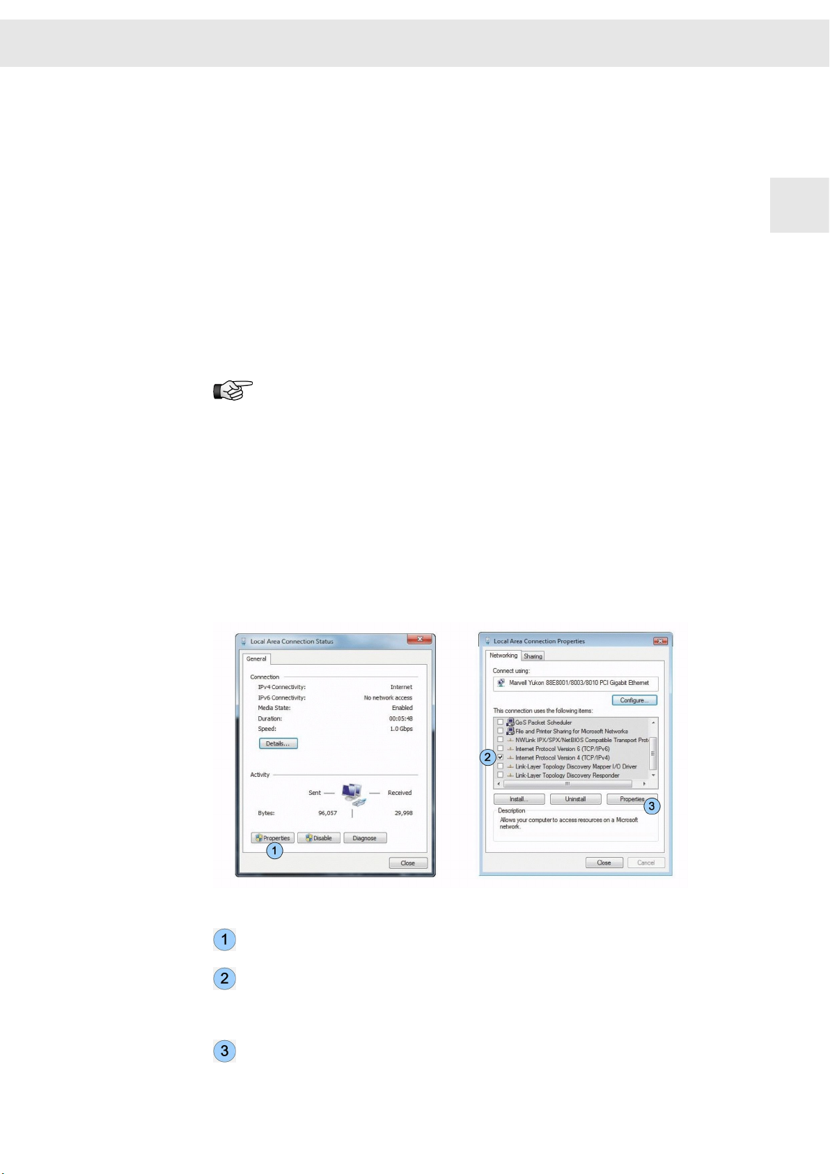
▶ Double click on the symbol for the second network card.
The window "Local Area Connection Status" appears.
Fig. 1: Connection status and properties of the second network card
Click on the button <Properties>.
The window "Local Area Connection Properties "appears.
Activate the option "Internet protocol (TCP/IPv4)" via the corresponding check
box. All other option are deactivated.
Ensure that only the option "Internet protocol version 4 (TCP/IPv4)" has been
activated, "Internet protocol version 6 (TCP/IPv6)" must not be activated!
Click on the button <Properties>.
WInstallation and Setup
CNC 8x.00 - Demo Kit 7
2
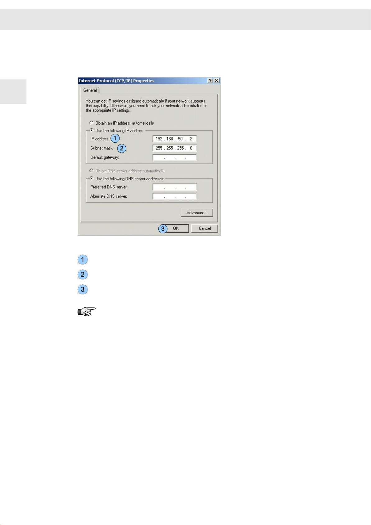
The window "Internet Protocol (TCP/IP) Properties" appears. Enter the IP
address of the 2nd network card into this window. You must ensure that both
network cards have different IP addresses.
Fig. 2: Enter IP address
IP address (PC) 192.168.50.2 (default)
Subnet mask: 255.255.255.0 (default)
Click on the button <Properties> to apply your entries.
The default IP address of the network card in the Motion Controller is:
192.168.50.1.
2.1.1.1 Notes for Windows 7
Starting from Windows 7 the TCP/IP stack of Windows has changed. This means that
Windows requires a quite long period (about 1min.) to re-establish a network connec‐
tion that was cut before (for example after a reset of the CPU card).
You can reduce the waitng time by binding the MAC address to its IP address.
Proceed as described in the following:
▶ Enter "
show mac
" in the buggy terminal.
The MAC address appears, e.g. "mac: 00:01:84:01:0C:2F".
▶ Start the prompt as administrator and enter the following text:
"
arp -s <IP address of the card> <MAC address of the card>
" bzw. mit o.g.
Adressen "
arp -s 192.168.50.1 00-01-84-01-0c-2f
"
Installation and Setup W
8 CNC 8x.00 - Demo Kit
2
2.2 Connection of the Hardware
2.2.1 Connection Example A
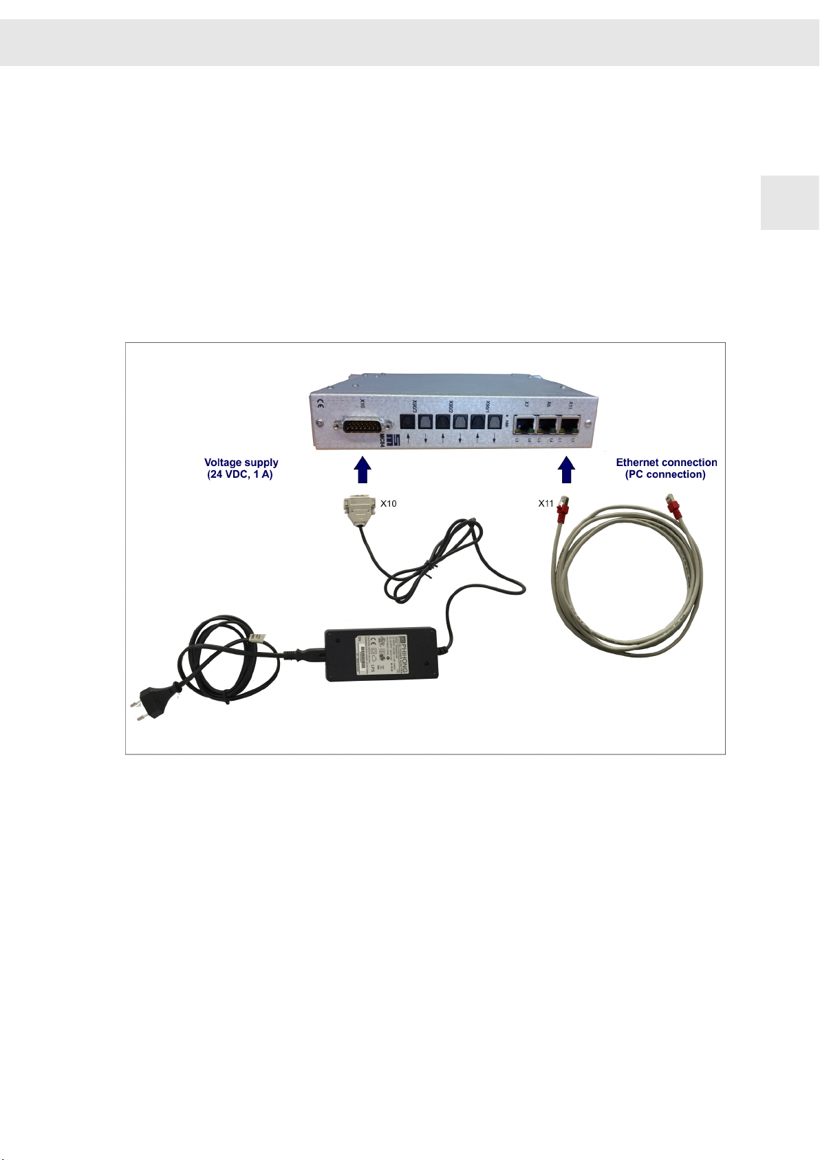
This connection example shows the connection of the motion controller, if delivered
with external power supply unit and network cable.
1. Connect the power cable to the external power supply unit and connect it to
mains.
2. Connect the power supply cable with X10 of the motion controller.
3. Connect the provided Ethernet cable with connector X11 of the motion controller
and with the network connection of the 2nd. network card of the PC or with the
LAN connector of the USB > Ethernet adapter.
Fig. 3: Connection of the Demo Kit hardware: connection example A
WInstallation and Setup
CNC 8x.00 - Demo Kit 9
2
2.2.2 Connection Example B
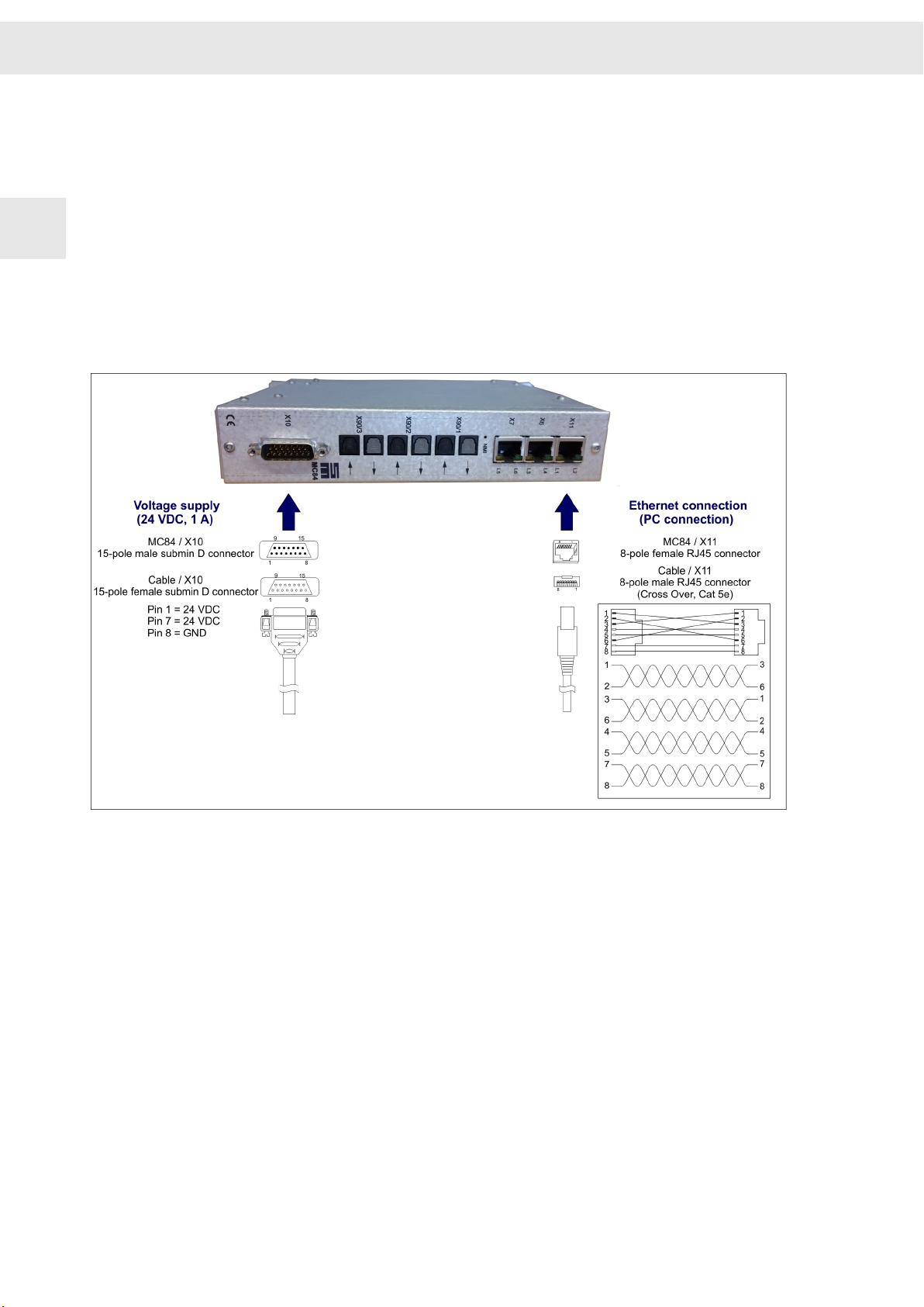
This connection example shows the connection of the motion controller, if delivered
with external power supply unit and network cable.
1. Mount a cable for the connection of the voltage supply to X10 according to the pin
assignment in the figure.
2. Connect the power supply cable with X10 of the motion controller and the adapter
to the mains socket.
3. Mount a cable for the connection of the PC according to the pin assignemt in the
figure (Cross Over, Cat 5e).
4. Connect the provided Ethernet cable with connector X11 of the motion controller
and with the network connection of the 2nd. network card of the PC or with the
LAN connector of the USB > Ethernet adapter.
Fig. 4: Connection of the Demo Kit hardware: connection example B
Installation and Setup W
10 CNC 8x.00 - Demo Kit
2
Este manual sirve para los siguientes modelos
2
Tabla de contenidos
Manuales populares de Placa madre de otras marcas


Telit Wireless Solutions
Telit Wireless Solutions SL869-3DR Manual de usuario

Gigabyte
Gigabyte GA-9IVDT Manual de usuario

Texas Instruments
Texas Instruments ADS8372EVM Manual de usuario

Commell
Commell MS-C73 Manual de usuario

IBT Technologies
IBT Technologies MB860 Manual de usuario

Nvidia
Nvidia TEGRA DG-04927-001_V01 Manual de usuario


