
shelolab SMO34HP-2 Manual de usuario
Installation and
Operation Manual
SMO34HP-2, SMO38HP-2
SMO14HP-2, SM10HP-2
Previously Designated:
HF25-2, HF37-2, HF15-2, HF10-2
SMO HIGH PERFORMANCE OVENS
220 - 240 Voltage

2 | P a g e
SMO High Performance Ovens 220 - 240 Voltage
Large Capacity
Installation and Operation Manual
Part number (Manual): 4861705
Revision: December 14, 2015
These ovens do not plug into a wall using a conventional plug. These ovens require
permanent connect wiring (also known as hardwiring).
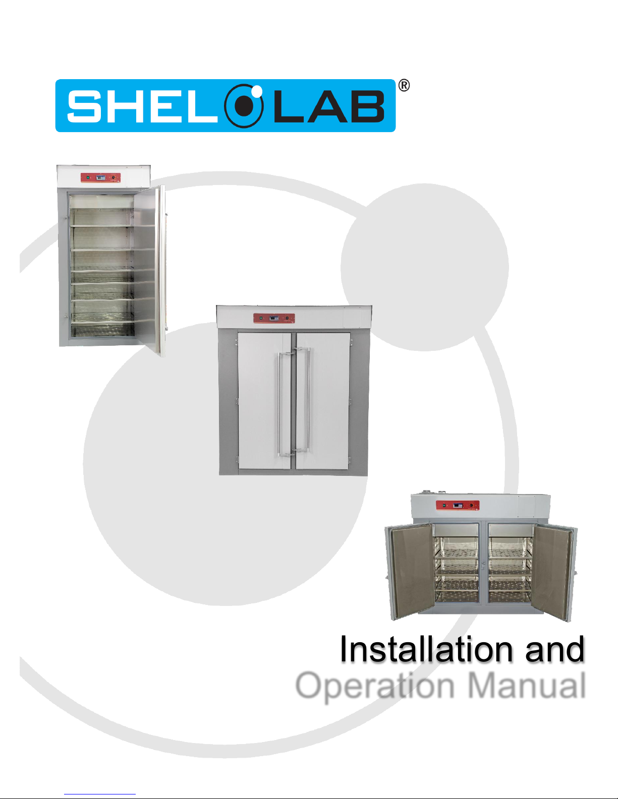
Pictured on front cover, left to right: SMO34HP-2, SMO38HP-2, SMO14HP-2
These units are TÜV CUE listed as forced air ovens for professional, industrial, or educational use
where the preparation or testing of materials is done at an ambient air pressure range of 22.14 –
31.3 inHg (75 –106 kPa) and no flammable, volatile, or combustible materials are being heated.
The units have been tested to the following requirements:
CAN/CSA C22.2 No. 61010-1:2012
CAN/CSA C22.2 No. 61010-2-010:2004 Reaffirmed: 2014-07
UL 61010-1:2012-05
UL 61010A-2-010:2002-03
EN 61010-1:2010
EN 61010-2-010:2014
Supplemented by: UL 61010-2-010:2015
SMO10HP-2

3 | P a g e
TABLE OF CONTENTS
INTRODUCTION...........................................................................................................................................4
General Safety Considerations.................................................................................................................4
Engineering Improvements .......................................................................................................................5
Contacting Assistance...............................................................................................................................5
RECEIVING YOUR OVEN............................................................................................................................6
Inspecting the Shipment............................................................................................................................6
Orientation Photos.....................................................................................................................................7
Recording Data Plate Information...........................................................................................................11
Temperature Reference Sensor Device .................................................................................................11
INSTALLATION..........................................................................................................................................12
Required Ambient Conditions .................................................................................................................12
Location Considerations..........................................................................................................................12
Power Source Requirements..................................................................................................................13
Power Feed Wiring..................................................................................................................................14
Lifting and Handling ................................................................................................................................14
Leveling...................................................................................................................................................14
Install the Oven .......................................................................................................................................15
Initial Cleaning.........................................................................................................................................15
Shelving Installation ................................................................................................................................15
GRAPHIC SYMBOLS.................................................................................................................................16
CONTROL PANEL OVERVIEW.................................................................................................................18
OPERATION...............................................................................................................................................21
Operating Precautions ............................................................................................................................21
Preparing the Oven for Use ....................................................................................................................24
Prepare for First Use Burn-In..................................................................................................................24
Set the Temperature Set Point................................................................................................................25
First Use Burn In .....................................................................................................................................26
Temperature Accuracy Verification.........................................................................................................28
Set the Over Temperature Limit..............................................................................................................30
OTL Activation During Normal Operations..............................................................................................31
Programming a Heating Profile...............................................................................................................31
Positive Venting of Exhaust ....................................................................................................................32
USER MAINTENANCE...............................................................................................................................34
Cleaning and Disinfecting .......................................................................................................................34
Electrical Components ............................................................................................................................35
Door Gaskets and Chamber Integrity......................................................................................................35
Calibrate the Temperature display..........................................................................................................36
UNIT SPECIFICATIONS.............................................................................................................................40
Weight .....................................................................................................................................................40
Dimensions..............................................................................................................................................40
Capacity ..................................................................................................................................................41
Shelf Capacity by Weight........................................................................................................................41
Temperature............................................................................................................................................41
Power ......................................................................................................................................................41
REPLACEMENT PART LIST.....................................................................................................................42

4 | P a g e
INTRODUCTION
Thank you for purchasing a Sheldon Manufacturing SMO forced air, high performance oven. We
know that in today’s competitive marketplace customers have many choices when it comes to
constant temperature equipment. We appreciate you choosing ours. Our continued reputation as a
leading laboratory product manufacturer rests with you. We stand behind our products and will be
here for you if you need us.
These ovens are intended for professional, industrial, and educational applications requiring
horizontal shelf space air flows. The ovens are not designed for use at hazardous or household
locations.
GENERAL SAFETY CONSIDERATIONS
Note: Failure to follow the guidelines and instructions in this manual may create a protection
impairment by disabling or interfering with the unit’s safety features. This can result in injury
or death.
Before you use your oven read this entire manual carefully to understand how to install, operate,
and maintain the oven in a safe manner. Keep this manual available for use by all oven operators.
Ensure that all operators are given appropriate training before the oven begins service.
Your oven and its recommended accessories have been designed and tested to meet strict safety
requirements. For continued safe operation of your oven, always follow basic safety precautions
including:
Follow any local or regional ordinances in your area regarding the use of this unit.
Only use the oven for its intended range of applications.
Use only approved accessories. Do not modify system components. Any alterations or
modifications to your oven may be dangerous and will void your warranty.
Always hardwire the unit power feed to a protective earth-grounded electrical source that
conforms to national and local electrical codes. If the unit is not grounded, parts such as,
knobs and controls may conduct electricity and cause serious injury.
Avoid damaging the power feed. Do not bend it excessively, step on it, place heavy objects
on it. A damaged power feed can easily become a shock or fire hazard. Never use a power
feed after it has been damaged.
Position the equipment so the end-user can quickly and easily disconnect or uncouple the
power feed in the event of an emergency.
Do not attempt to move the unit while in operation or before the unit has cooled.

5 | P a g e
INTRODUCTION (CONTINUED)
ENGINEERING IMPROVEMENTS
Sheldon Manufacturing continually improves all of its products. As a result, engineering changes
and improvements are made from time to time. Therefore, some changes, modifications, and
improvements may not be covered in this manual. If your unit’s operating characteristics or
appearance differs from those described in this manual, please contact your Shel Lab dealer or
customer service representative for assistance.
CONTACTING ASSISTANCE
If you are unable to resolve a technical issue with the oven, please contact Sheldon Technical
Support. Phone hours for Sheldon Technical Support are 6am –4:30pm Pacific Coast Time (west
coast of the United States, UTC -8).
Please have the following information ready when calling or emailing Technical Support: the model
number and the serial number. These will be found on the unit’s data plate, which is located on
the back of the unit at the top right, next to the power supply as mandated by regulatory
requirement. See page 7.
Sheldon Manufacturing INC.
P.O. Box 627
Cornelius, OR 97113
6 | P a g e
RECEIVING YOUR OVEN
Before leaving the factory, all ovens are packaged in high-quality shipping materials to provide
protection from transportation-related damage. When a unit departs our factory, safe delivery
becomes the responsibility of the carrier. Damage sustained during transit is not covered by the
manufacturing defect warranty.
This makes it important that you inspect your oven for concealed loss or damage to its interior and
exterior when receiving it. If you find any damage to the unit, follow the carrier’s procedure for
claiming damage or loss.
The orientation photos on the immediately following pages may serve as useful references when
inspecting the oven.
Carefully check all packaging before discarding. Save the shipping carton until you are certain that
the unit and its accessories function properly.
INSPECTING THE SHIPMENT
Carefully inspect the shipping carton for damage. Report any damage to the carrier service that
delivered the SMOHP oven. If the carton is not damaged, open the carton and remove the
contents. The unit should come with an Installation and Operation Manual, and a Certificate of
Compliance.
Verify that the correct number of shelves, shelf slides, and leveling feet have been included (see
the following table for quantities).
Included accessories
Model
Shelves
Shelf Slides / Clips
Leveling Feet
SMO10HP-2
3
12 Clips
4
SMO14HP-2
6
24 Clips
4
SMO34HP-2
6
24 Clips
4
SMO38HP-2
12
48 Clips
4
Carefully check all packaging before discarding. Save the shipping carton until you are certain that
the unit and its accessories function properly.
7 | P a g e
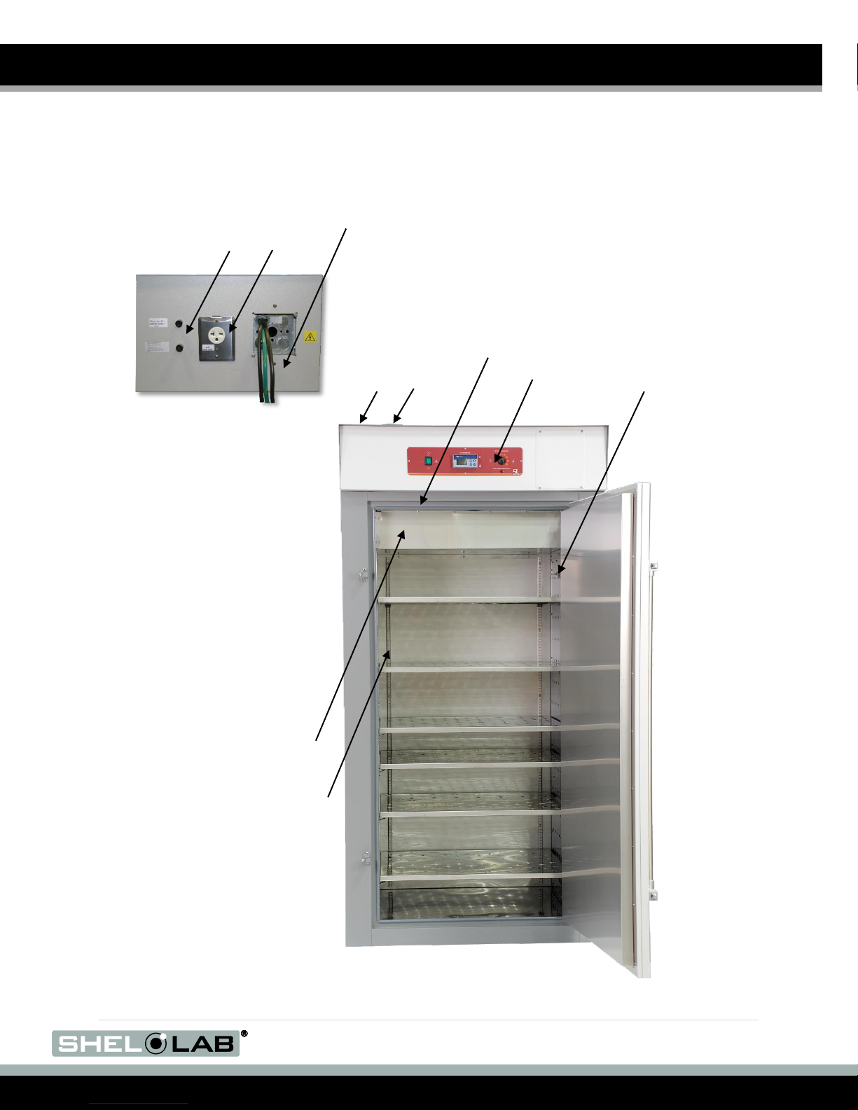
Figure 1: SMO34HP-2
RECEIVING YOUR OVEN (CONTINUED)
ORIENTATION PHOTOS
Permanent Connect Wire Braid
6 gauge, 6 inches (15 cm)
Exhaust
Vent
Intake
Vent
Power Panel (Back)
Control Panel
Temperature
Sensor Probes
Chamber Gasket
Power Exhaust
Outlet 6-20R
Fuse Holders for External
Receptacle (2 amps each)
Chamber Ceiling Liner
Power Supply Feed
Shelf Standard Mounting
Rail
8 | P a g e
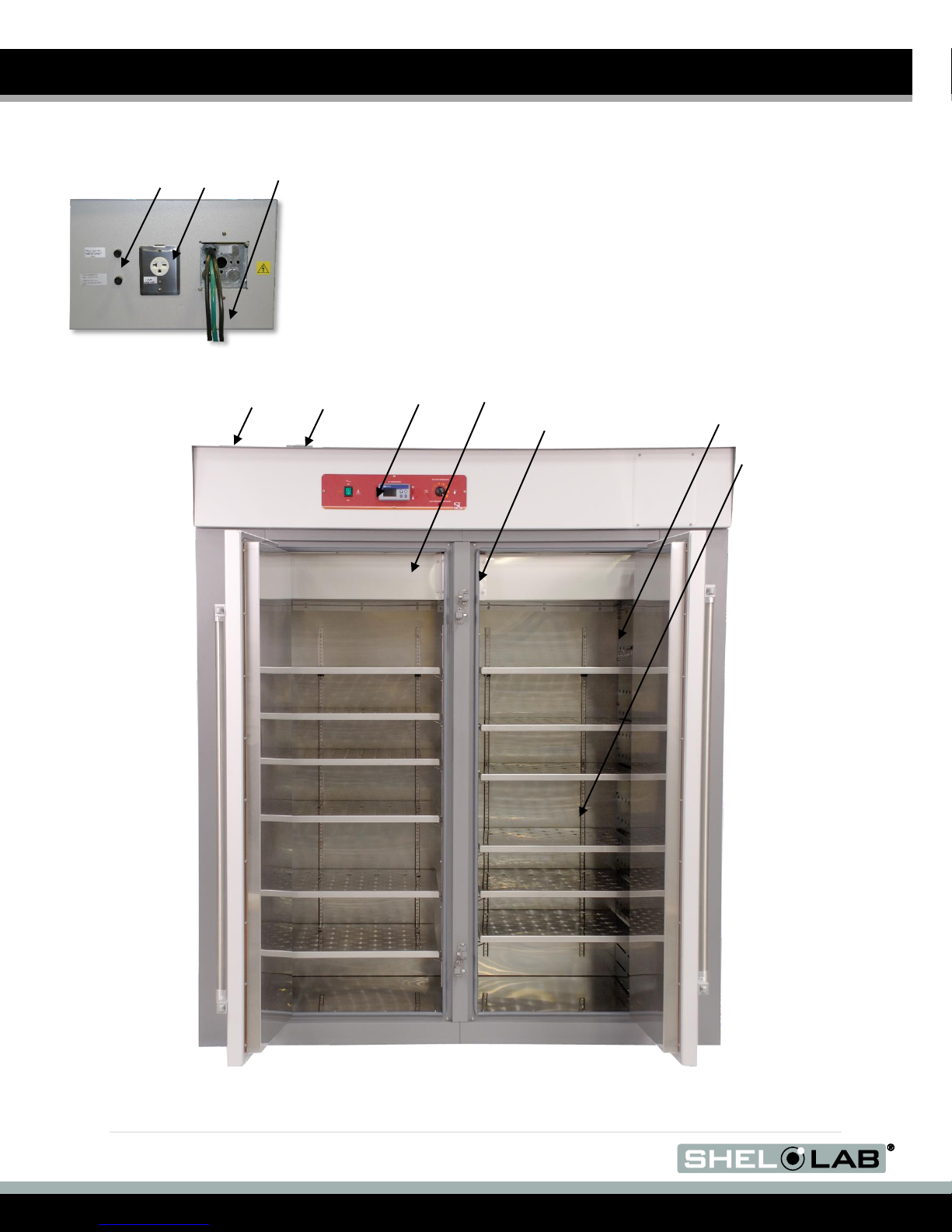
Figure 2: SMO38HP-2
RECEIVING YOUR OVEN (CONTINUED)
Power Panel
(Back)
Temperature Sensor
Probes
Chamber Ceiling Liner
Permanent Connect Wire Braid 6
gauge, 6 inches (15 cm)
Control Panel
Exhaust Vent
Intake Vent
Chamber Liner Gasket
Shelf Standard
Mounting Rail
Fuse Holders for External
Receptacle (2 amps each)
Power Exhaust
Outlet 6-20R
Power
Supply Feed

9 | P a g e
Figure 3: SMO14HP-2
RECEIVING YOUR OVEN (CONTINUED)
Intake Vent
Exhaust Vent
Control Panel
Chamber Gasket
Temperature
Sensor Probes
Chamber Ceiling Liner
Power Panel (Back)
Permanent Connect Wire Braid
10 gauge, 6 inches (15 cm)
Fuse Holders for External
Receptacle (2 amps each)
Power Exhaust
Outlet 6-20R
Power
Supply Feed
Shelf Standard Mounting Rail
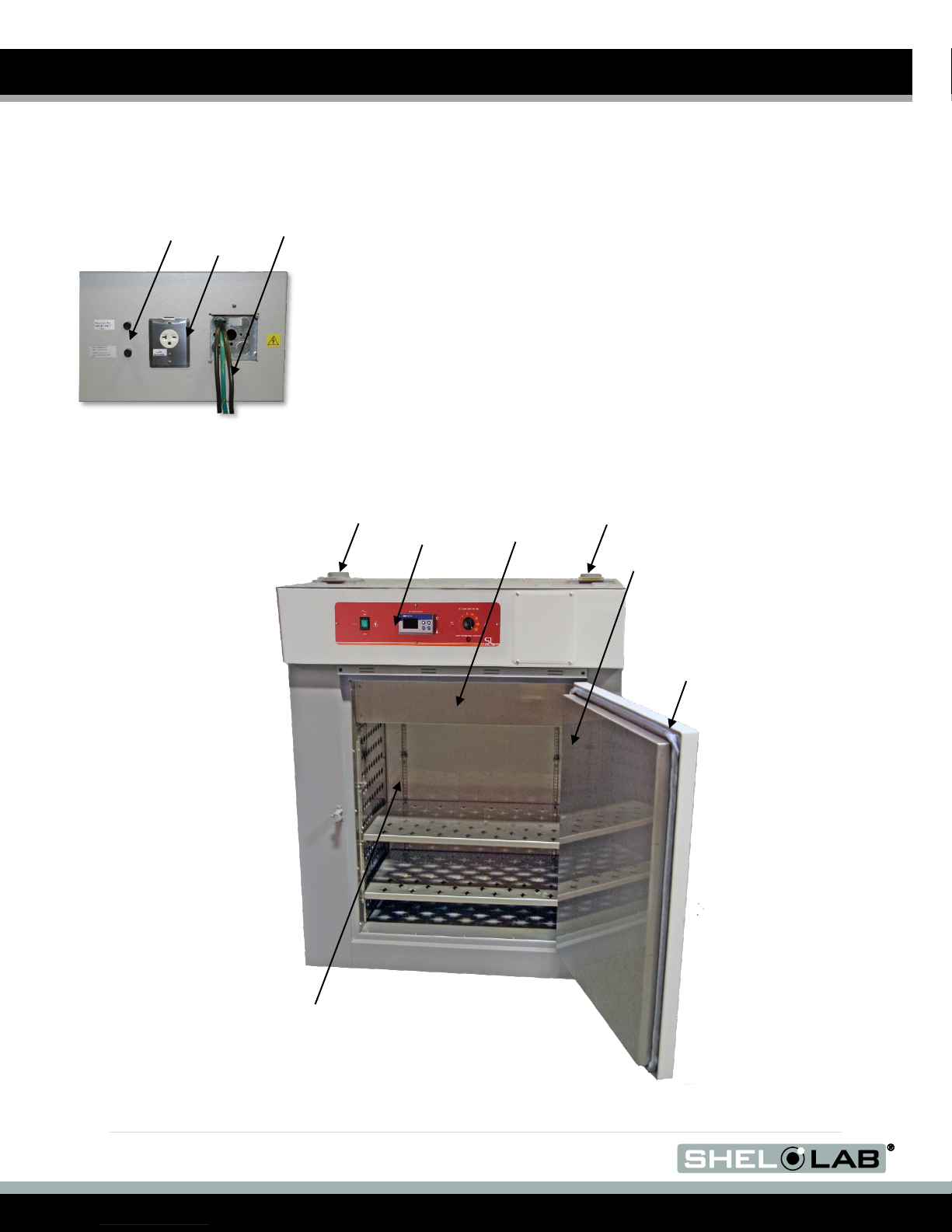
10 | P a g e
RECEIVING YOUR OVEN (CONTINUED)
Shelf Standard Mounting Rail
Power Panel
(Back)
Fuse Holders for External
Receptacle (2 amps each)
Power Exhaust
Outlet 6-20R
Intake Vent
Exhaust Vent
Control
Panel
Chamber Ceiling
Liner
Door Gasket
Permanent Connect Wire Braid
10 gauge, 6 inches (15 cm)
Power
Supply Feed
Temperature
Sensor Probes
(In Chamber)
Figure 4: SMO10HP-2
Este manual sirve para los siguientes modelos
3
Tabla de contenidos
Otros manuales de Horno de shelolab

shelolab
shelolab SG02 Manual de usuario

shelolab
shelolab SVAC1E Manual de usuario

shelolab
shelolab SMO5HP-2 Manual de usuario

shelolab
shelolab SGO1-2 Manual de usuario

shelolab
shelolab SMO5HP-2 Manual de usuario

shelolab
shelolab E1310 Manual de usuario

shelolab
shelolab SMO14-2 Manual de usuario

shelolab
shelolab SGO3 Manual de usuario

shelolab
shelolab SMO1E Manual de usuario

shelolab
shelolab SMO3 Manual de usuario


