Sercomm UE Tester Manual de usuario

Verizon LTE
UE Tester
Model: INTTP202134134
Quick Installation Guide
Manufacture By:
Sercomm Corporation
8F, No. 3-1, YuanQu Street, Nankang,
Taipei 115, Taiwan, R.O.C.


i
Table of Contents
CHAPTER 1 INTRODUCTION .............................................................................................1
Package Contents ..............................................................................................................1
Key Feature........................................................................................................................1
LEDs...................................................................................................................................2
Rear Panel..........................................................................................................................3
CHAPTER 2 INITIAL INSTALLATION..............................................................................4
Procedure...........................................................................................................................4
CHAPTER 3 SPECIFICATIONS ...........................................................................................5
General Specification........................................................................................................5
RF Characteristics.............................................................................................................5
Regulatory Requirements.................................................................................................6
Safety Information ............................................................................................................7
Device Surface Cleaning...................................................................................................9
Accessories .......................................................................................................................10


1
Chapter 1
Introduction
This Chapter provides an overview of the device's features and capabilities.
The LTE INTTP202134134 series UE Tester is a Desktop Small Cell LTE Device Tester
handles multiple scenarios, running different protocols simultaneously, and provides a com-
plete, independent solution.
Package Contents
The following items should be included:
If any of the above items are damaged or missing, please contact your dealer immediately.
Key Feature
•Designed for indoor lab test equipment deployment
•Dual Intel T3100 chipset
•Total 2GB RAM (1 GB RAM per each T3100)
•Support up to 4 concurrent LTE bands
•Support 4 Gigabit Ethernet Ports with RJ45 connector
•Support 8 External RF antenna with Transmission output at 17dBm per RF ports
•Support 2 External RF GPS antenna
1

2
LEDs
Top-mounted LED
POWER (Red) On - Power On/Normal Operation
Off - Power off
WAN1 (Red/Green) On Green - CPU1 LAN active
On Red - CPU1 LAN inactive
WAN2 (Red/Green) On Green – CPU2 LAN active
On Red – CPU2 LAN inactive
RF1 (Red/Green) On Green – Band 13 in service
On Red – Band 13 RF not in service
RF2 (Red/Green) On Green – Band 4 in service
On Red – Band 4 RF not in service
RF3 (Red/Green) On Green – Band 13 in service
On Red – Band 13 RF not in service
RF4 (Red/Green) On Green – Band 4 in service
On Red – Band 4 RF not in service
GPS1 (Red/Green) On Green – GPS in service
On Red – GPS RF not in service
GPS2 (Red/Green) On Green – GPS in service
On Red – GPS RF not in service

3
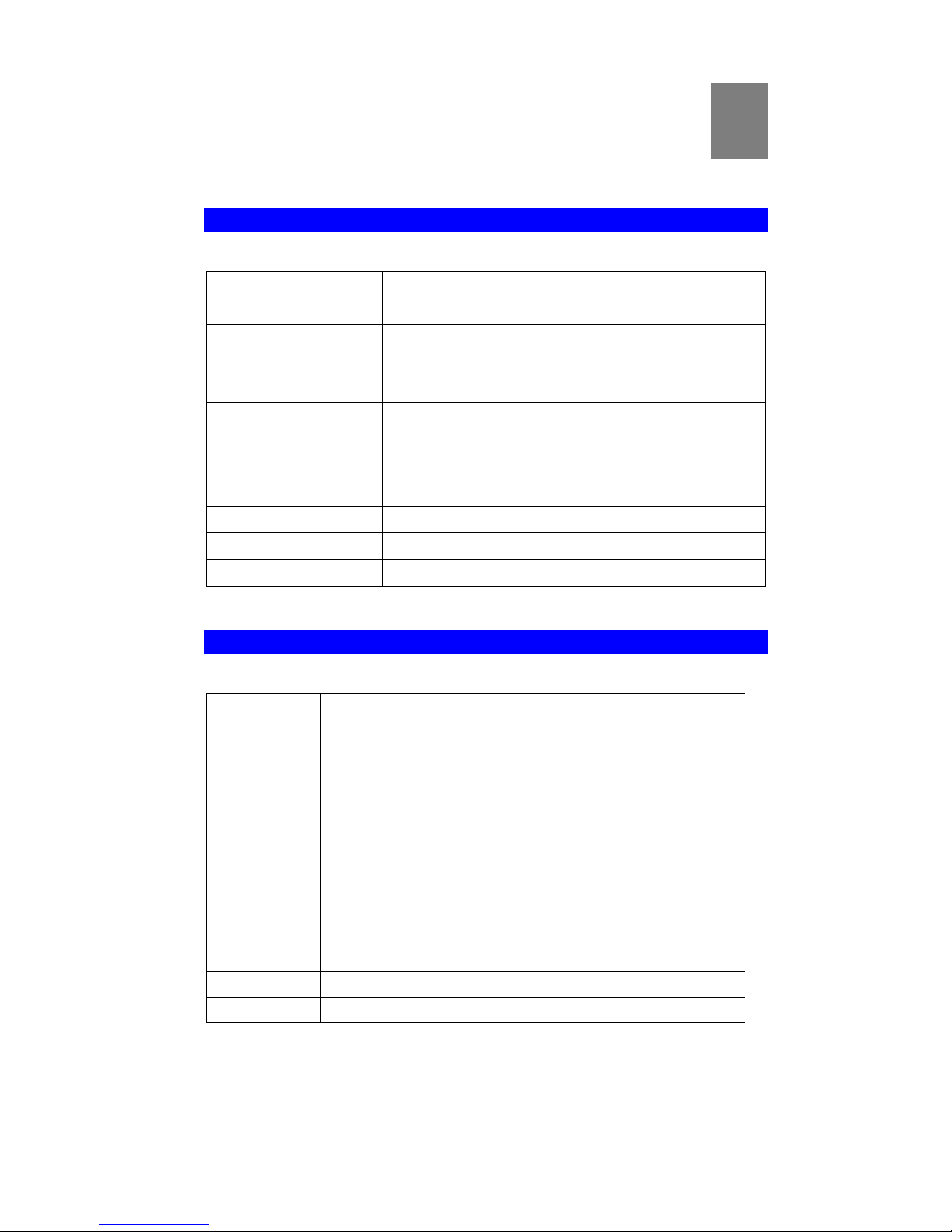
Rear Panel
Power Input: 12 Vdc, 9A, Power Jack to Power Adaptor
Reset 1 This button is used to reset or restore to factory default for CPU1
Reset 2 This button is used to reset or restore to factory default for CPU1
Ethernet Use standard LAN cable (RJ45 connectors) to connect to backhaul
/broadband router
RF1 Band 4 SMA connection for Band 4 External Antennas
RF2 Band 13 SMA connection for Band 13 External Antennas
RF3 Band 4 SMA connection for Band 4 External Antennas
RF4 Band 13 SMA connection for Band 13 External Antennas
GPS1 SMA connection for GPS1 External Antennas
GPS2 SMA connection for GPS2 External Antennas

4
Chapter 2
Initial Installation
This Chapter covers the software installation of the device.
Procedure
1. External Antenna
Connect the external antennas (total 8 included in the package) to antenna connector
ports.
2. Power Up
Connect the supplied power adapter to the UE Tester. Use only the power adapter pro-
vided. Using a different one may cause hardware damage.
3. Connect LAN Cable
Use a standard LAN cable to connect the device to the Ethernet port on the UE Tester
and to LAN/PC
4. Check the LEDs
The Power LED should be ON.
WAN1, WAN2 LED should be ON
RF1/RF2/RF3/RF4 should be ON depend on the UE test case scenario
2
5
Chapter 3
Specifications
General Specification
Connectivity -10x SMA RF connector for External Antennas
-Four Gigabit Ethernet LAN ports
Power Supply External Power Adapter:
Input: AC100~240V~1.6A, 50Hz/60Hz, Altitude 0 to 5000
Meters
Output: 12 Vdc, 9A
Operating Requirement Operating Temp. 0ºC to 40ºC
Storage Temp. -5ºC to 45ºC
Operating Humidity 5% to 90% Non-Condensing
Storage Humidity 5% to 95% Non-Condensing
Reset button Two
LED 9 LED for Status.
Housing 426mm(W)x236mm(H)x65mm(D)
RF Characteristics
Parameter UMTS
Frequency FDD:
Band 13: DL/UL: 746~756MHz /777~787MHz
Band 4: DL/UL: 2100~2155MHz/1710~1755MHz
Bandwidth CPU1:
2CA Band 4 + Band 13 (10M+10M)
2CA Band 4 + Band 13 (20M+10M)
CPU2:
2CA Band 4 + Band 13 (10M+10M)
2CA Band 4 + Band 13 (20M+10M)
Beamwidth External Omni Antennas
Power rating +17dBm(50mW) per Antenna.
3

6
Regulatory Requirements
類別 Area Standard Note
EMC USA FCC Part 15B
RF USA FCC Part
24E/27/22H/27F/PAG
FCC Statement
This device complies with Part 15 of the FCC Rules. Operation is subject to the following two
conditions: (1) This device may not cause harmful interference, and (2) this device must accept
any interference received, including interference that may cause undesired operation.
This equipment has been tested and found to comply with the limits for a Class B digital
device, pursuant to Part 15 of the FCC Rules. These limits are designed to provide reasonable
protection against harmful interference in a residential installation. This equipment generates,
uses and can radiate radio frequency energy and, if not installed and used in accordance with
the instructions, may cause harmful interference to radio communications. However, there is
no guarantee that interference will not occur in a particular installation. If this equipment does
cause harmful interference to radio or television reception, which can be determined by turning
the equipment off and on, the user is encouraged to try to correct the interference by one of the
following measures:
-Reorient or relocate the receiving antenna. -Increase the separation between the equipment
and receiver.
-Connect the equipment into an outlet on a circuit different from that to which the receiver is
connected.
-Consult the dealer or an experienced radio/TV technician for help.
FCC Caution: Any changes or modifications not expressly approved by the party responsible
for compliance could void the user's authority to operate this equipment. This transmitter must
not be co-located or operating in conjunction with any other antenna or transmitter.
Radiation Exposure Statement:
This equipment complies with FCC radiation exposure limits set forth for an uncontrolled
environment. This equipment should be installed and operated with minimum distance 20cm
between the radiator & your body.
Este manual sirve para los siguientes modelos
1
Tabla de contenidos
Manuales populares de Equipo de prueba de otras marcas

SMART
SMART KANAAD SBT XTREME 3G Series Manual de usuario

Agilent Technologies
Agilent Technologies BERT Serial Manual de usuario

Agilent Technologies
Agilent Technologies N3280A Manual de usuario

Vernier
Vernier Go Direct Voltage Manual de usuario

Lifeloc
Lifeloc R.A.D.A.R. Manual de usuario

Fluke
Fluke T5-600 Instrucciones de funcionamiento e instalación


